Scaffold screen grinding and leveling machine

A scaffolding and leveling machine technology is applied in the field of grinding and processing, which can solve the problems of low work efficiency and large labor consumption, and achieve the effects of improving work efficiency, reducing consumption and ensuring health.

Active Publication Date: 2019-01-11
重庆玖和惠鼎建筑劳务有限公司
View PDF8 Cites 5 Cited by
  • Summary
  • Abstract
  • Description
  • Claims
  • Application Information

AI Technical Summary

Problems solved by technology

[0005] The present invention intends to provide a scaffolding net plate grinding and leveling machine to solve the problems that the existing net plate grinding needs to consume a lot of labor and work efficiency is low

Method used


Image

  • Scaffold screen grinding and leveling machine
  • Scaffold screen grinding and leveling machine
  • Scaffold screen grinding and leveling machine

Examples


Embodiment 1

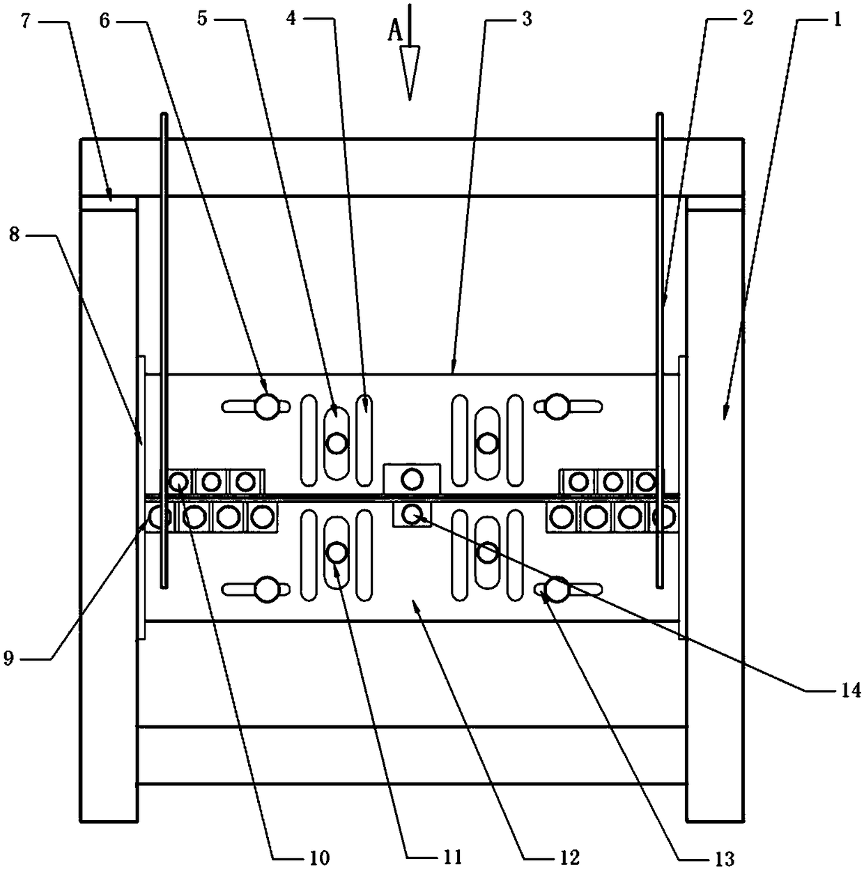
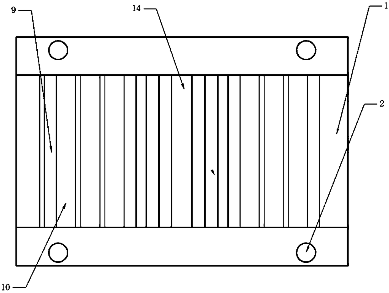
[0032] Scaffold net plate grinding and leveling machine, basically as attached figure 1 And attached figure 2 As shown, the frame 1 is included, the front and back of the frame 1 are provided with clamping mechanisms, and the clamping structures include an upper clamping plate 3 and a lower clamping plate 12 . The upper part of the frame 1 is provided with a spacer 7 for stabilizing the frame structure of the frame 1 .

[0033] Both the upper clamping plate 3 and the lower clamping plate 12 are vertically slidingly connected with the frame 1, and the guide rail 8 is also fixed on the frame 1, and the two ends of the upper clamping plate 3 and the lower clamping plate 12 are located in the guide rail 8, The upper clamping plate 3 and the lower clamping plate 12 are guided by the guide rail 8, four lead screws 2 are fixed on the frame 1, and the nut seats of the lead screw 2 are respectively connected with the corresponding upper clamping plate 3 and the lower clamping plate ...

Embodiment 2

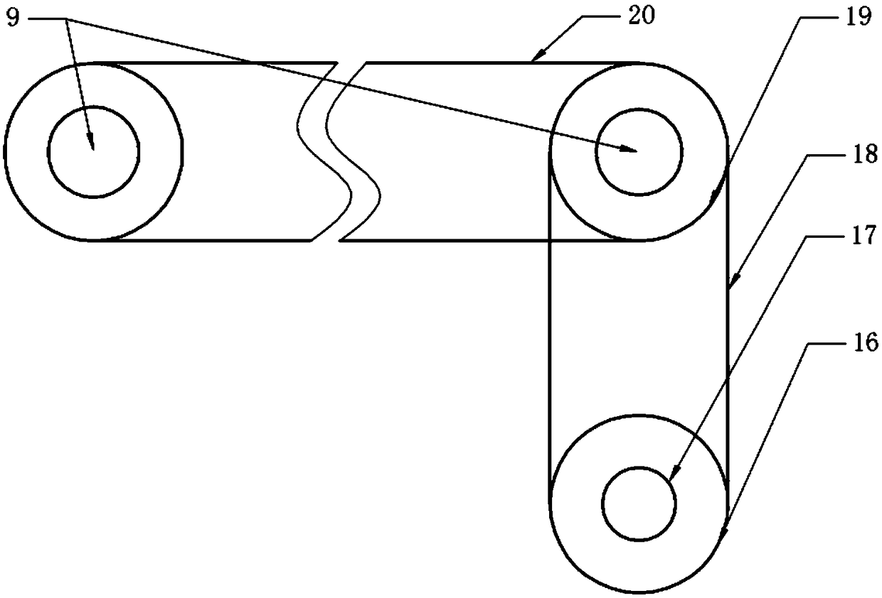
[0045] The difference from Embodiment 1 is that, as attached Image 6 As shown, the connecting end of the tensioning wheel 6 is slidably connected with the chute 13, and the side of the tensioning wheel 6 away from the guide groove 5 is provided with an air box 26 installed on the frame 1, and the air box 26 is horizontally slidably connected with The piston plate is fixed with the piston rod 261 fixedly connected with the tensioning wheel 6, and the air box 26 on the left side of the piston plate is connected with an air intake check valve 263 and an air outlet check valve 262, and the intake check valve 263 Under the action of pressure, the gas outside the gas box 26 enters the gas box 26 through the intake check valve 263, and the gas outlet check valve 262 is subjected to pressure, and the gas inside the gas box 26 will be discharged through the gas outlet check valve 262, and the tensioner 6. A spring against the sliding groove 13 is provided on one side close to the moun...


PUM


Abstract

The invention relates to the technical field of grinding machining, and discloses a scaffold screen grinding and leveling machine. The scaffold screen grinding and leveling machine comprises a rack. Clamping mechanisms are arranged on the front face and the back face of the rack. Each clamping mechanism comprises an upper clamping plate and a lower clamping plate. Upper leveling roller sets are arranged between the two ends of the two upper clamping plates, an upper buffer roller is arranged between the middles of the two upper clamping plates, and upper grinding rollers are arranged on the two sides of the upper buffer roller correspondingly. A lower buffer roller is arranged between the middles of the two lower clamping plates, lower grinding rollers are arranged on the two sides of thelower buffer roller correspondingly, and the upper grinding rollers and the lower grinding rollers form grinding opposite rollers. A first motor is arranged on the rack, lower leveling rollers at thetwo ends are driven by the first motor, a driving gear is arranged on the lower leveling roller set at one end, and a driven gear is arranged on the upper buffer roller set corresponding to the lowerleveling roller set at the end. Multiple second motors are arranged on the rack. The scaffold screen grinding and leveling machine is simple in structure, screens can be ground well, and the work efficiency of grinding can be improved.

Description

technical field [0001] The invention relates to the technical field of grinding and processing, in particular to a grinding and leveling machine for scaffolding net plates. Background technique [0002] Scaffolding is a platform built to ensure the smooth progress of various construction projects. It can be divided into outer scaffolding and inner scaffolding according to the location of the setting. Traditional scaffolding will be equipped with protective nets to protect the safety of operators, but the load-bearing capacity of the current protective nets is poor, and it is inevitable that debris will fall onto the protective nets during the construction process to reduce the safety factor of the protective nets. Unfortunately, the personnel fell onto the protective net due to an operation error. Since the safety factor of the protective net is reduced, it is difficult to guarantee the safety of the operator. [0003] In order to solve the safety problems of the protective...

Claims


Application Information

Patent Timeline
IPC IPC(8): B24B27/00B24B41/06B24B41/00B24B47/12B24B7/17B24B55/06B24B55/00B21D1/02
CPCB21D1/02B24B7/17B24B27/00B24B27/0076B24B41/007B24B41/06B24B47/12B24B55/00B24B55/06
Inventor 李栋
Owner 重庆玖和惠鼎建筑劳务有限公司
Why Eureka
Try Eureka