Concrete mixing plant

A mixing station and concrete technology, applied in mixing plants, clay preparation equipment, mixing operation control, etc., can solve the problems of measuring and transportation time affecting the production efficiency of mixers, and achieve good dust removal effect, easy maintenance, and reasonable structural layout.

Pending Publication Date: 2019-01-11
GUANGXI DADU CONCRETE GROUP
View PDF13 Cites 7 Cited by
  • Summary
  • Abstract
  • Description
  • Claims
  • Application Information

AI Technical Summary

Problems solved by technology

Because the aggregate bin of the mixing station is far away from the mixer, it generally takes at least 15 seconds to complete the measurement of aggregate ingredients, and it takes at least 20 seconds to completely transport the material to the middle of the aggregate through th

Method used


Image

  • Concrete mixing plant
  • Concrete mixing plant
  • Concrete mixing plant

Examples


Embodiment 1

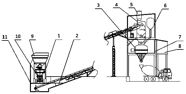
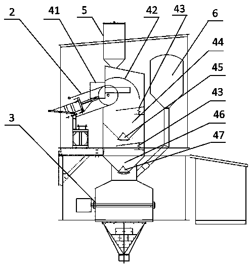
[0032] like Figure 1-3 As shown, a concrete mixing plant includes a gravel input station 1, a conveyor belt 2, a storage bin 4, a stirring device 3, a steel structure frame 7 and a control system box 8; the gravel input station 1 is located on the top of the conveyor belt 2 ; The conveyor belt 2 is connected to the side of the hopper 4; the stirring device 3 is installed below the hopper 4; the stirring device 3 is installed on the steel frame 7; the control system box 8 is located at The side of the stirring device 3; the described storage bin 4 is sequentially provided with an arc plate 42, a secondary storage hopper 44 and a primary storage hopper 46 from top to bottom; the primary storage hopper 46 and the secondary storage The first unloader 47 and the second unloader 45 are respectively provided at the bottom of the hopper 44; the outside of the hopper 4 is provided with a dust removal device; the first-level hopper 46 and the second-level hopper 44 are equidistant Arr...

Embodiment 2

[0044] like Figure 1-3 As shown, a concrete mixing plant includes a gravel input station 1, a conveyor belt 2, a storage bin 4, a stirring device 3, a steel structure frame 7 and a control system box 8; the gravel input station 1 is located on the top of the conveyor belt 2 ; The conveyor belt 2 is connected to the side of the hopper 4; the stirring device 3 is installed below the hopper 4; the stirring device 3 is installed on the steel frame 7; the control system box 8 is located at The side of the stirring device 3; the described storage bin 4 is sequentially provided with an arc plate 42, a secondary storage hopper 44 and a primary storage hopper 46 from top to bottom; the primary storage hopper 46 and the secondary storage The first unloader 47 and the second unloader 45 are respectively provided at the bottom of the hopper 44; the outside of the hopper 4 is provided with a dust removal device; the first-level hopper 46 and the second-level hopper 44 are equidistant Arr...

Embodiment 3

[0056] like Figure 1-3 As shown, a concrete mixing plant includes a gravel input station 1, a conveyor belt 2, a storage bin 4, a stirring device 3, a steel structure frame 7 and a control system box 8; the gravel input station 1 is located on the top of the conveyor belt 2 ; The conveyor belt 2 is connected to the side of the hopper 4; the stirring device 3 is installed below the hopper 4; the stirring device 3 is installed on the steel frame 7; the control system box 8 is located at The side of the stirring device 3; the described storage bin 4 is sequentially provided with an arc plate 42, a secondary storage hopper 44 and a primary storage hopper 46 from top to bottom; the primary storage hopper 46 and the secondary storage The first unloader 47 and the second unloader 45 are respectively provided at the bottom of the hopper 44; the outside of the hopper 4 is provided with a dust removal device; the first-level hopper 46 and the second-level hopper 44 are equidistant Arr...


PUM

PropertyMeasurementUnit
Thicknessaaaaaaaaaa

Abstract

The invention discloses a concrete mixing plant. The concrete mixing plant comprises a sand stone input station, a conveying belt, a material waiting bin, a mixing device, a steel structure frame anda control system box. The sand stone input station is arranged on the top of the conveying belt. The conveying belt is connected to the side edge of the material waiting bin. The mixing device is arranged below the material waiting bin. The control system box is arranged on the side edge of the mixing device. An arc plate, a second-level material waiting hopper and a first-level material waiting hopper are sequentially arranged in the material waiting bin from top to bottom. A first unloading device and a second unloading device are arranged at the bottom of the first-level material waiting hopper and the bottom of the second-level material waiting hopper correspondingly. A dust removal device is arranged on the outer side of the material waiting bin. A PLC control system is arranged in the control system box. The PLC is electrically connected with the sand stone input station, the conveying belt, the mixing device, the first unloading device and the second unloading device. The concrete mixing plant which is uniform in mixing, capable of reducing raise dust, high in work efficiency and capable of meeting the environment protection requirement is provided.

Description

technical field [0001] The invention belongs to the field of construction machinery and equipment, and in particular relates to a concrete mixing station. Background technique [0002] With the development of ready-made concrete industry, ready-made concrete enterprises are also increasing, and the market competition is fierce, so only by improving production efficiency can we gain a firm foothold. In addition, in terms of environmental protection, society has higher and higher requirements for environmental protection, and enterprises must also improve the environmental performance of production equipment accordingly. [0003] The prior art discloses a new type of CNC concrete mixing plant with application number CN201620281475.7, which includes a sandstone input station, a water supply system, a mixer, and a control system box. The sandstone input station is connected to a conveyor belt, and the conveyor belt is connected to There is a funnel, the mixer is installed under...

Claims


Application Information

Patent Timeline
IPC IPC(8): B28C7/00B28C7/04B28C9/02
CPCB28C7/0007B28C7/0069B28C7/0076B28C7/044B28C7/0481B28C9/02
Inventor 陆乔韦炳军甘启盛伍志滨李志雄雷振宁黄剑锋陆子平岑晓梅曾添陈其锋
Owner GUANGXI DADU CONCRETE GROUP
Why Eureka
Try Eureka