
Electric vehicle wireless charging system and method

A wireless charging, electric vehicle technology, applied in electric vehicle charging technology, electric vehicles, charging stations, etc., can solve the problems of discrete design and large volume

Active Publication Date: 2021-06-08
UNITED AUTOMOTIVE ELECTRONICS SYST
View PDF0 Cites 0 Cited by
  • Summary
  • Abstract
  • Description
  • Claims
  • Application Information

AI Technical Summary

Problems solved by technology

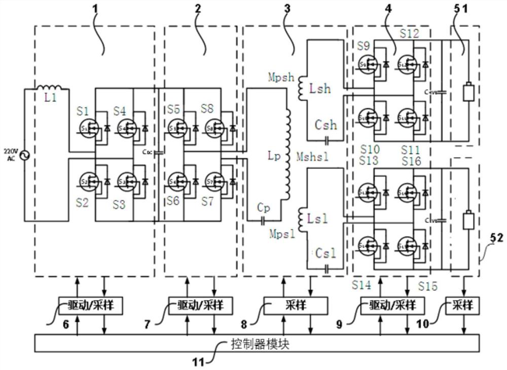
[0008] The purpose of the present invention is to provide a wireless charging system and method for electric vehicles to solve the problems of large volume and discrete design of the existing wireless charging system for high and low voltage batteries

Method used


Image

  • Electric vehicle wireless charging system and method
  • Electric vehicle wireless charging system and method
  • Electric vehicle wireless charging system and method

Examples


Embodiment 1

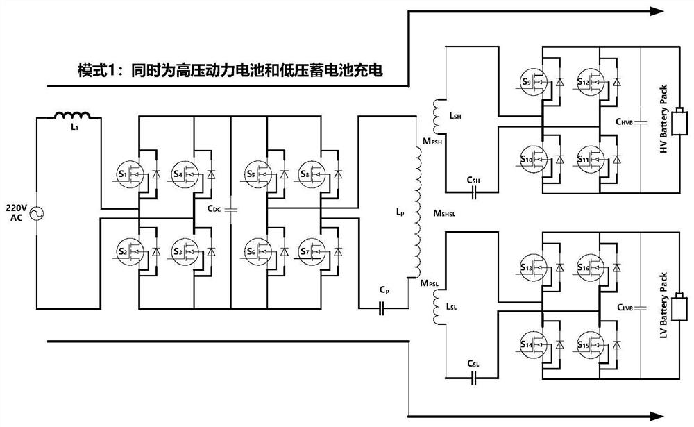
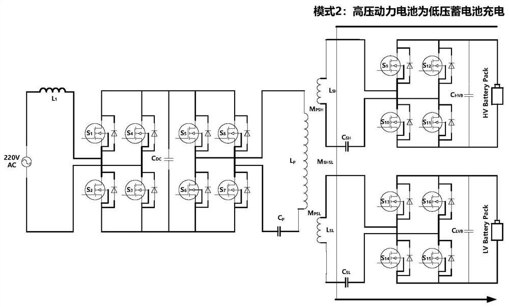
[0061] This embodiment provides a wireless charging system for electric vehicles, such as figure 1 As shown, the electric vehicle wireless charging system includes a sequentially connected power factor correction module 1, an H-bridge inverter module 2, a magnetic energy coupling mechanism module 3, and an active rectification module 4, and also includes high-voltage power supplies connected to the active rectification module 4 respectively. Battery module 51 and low-voltage battery module 52, wherein: as figure 2 As shown, the 220V mains power grid supplies power to the high voltage battery module 51 and the low voltage battery module 51 through the power factor correction module 1, the H bridge inverter module 2, the magnetic energy coupling mechanism module 3 and the active rectification module battery module 52 charging; as image 3 As shown, the high-voltage battery module 51 charges the low-voltage battery module 52 through the magnetic energy coupling mechanism module...

Embodiment 2

[0076] This embodiment also provides a wireless charging method for electric vehicles. The wireless charging method for electric vehicles includes: the 220V mains power grid supplies power to the high-voltage battery module through a power factor correction module, an H-bridge inverter module, a magnetic energy coupling mechanism module, and an active rectification module. charging with the low-voltage battery module; the high-voltage battery module charges the low-voltage battery module through the magnetic energy coupling mechanism module and the active rectification module; the low-voltage battery module charges the low-voltage battery module through the magnetic energy coupling mechanism module and the active rectification module Charge the high-voltage battery module; the high-voltage battery module feeds energy back to the 220V mains grid through the power factor correction module, the H-bridge inverter module, the magnetic energy coupling mechanism module and the active r...


PUM


Abstract

The present invention provides a wireless charging system and method for an electric vehicle, comprising a sequentially connected power factor correction module, an H-bridge inverter module, a magnetic energy coupling mechanism module and an active rectification module, respectively connecting the high-voltage battery module and the active rectification module of the active rectification module A low-voltage battery module, the 220V mains power grid charges the high-voltage battery module and the low-voltage battery module through the power factor correction module, the H-bridge inverter module, the magnetic energy coupling mechanism module and the active rectification module; The high-voltage battery module charges the low-voltage battery module through the magnetic energy coupling mechanism module and the active rectification module; the low-voltage battery module charges the high-voltage battery module through the magnetic energy coupling mechanism module and the active rectification module Charging: the high-voltage battery module feeds energy back to the 220V mains grid through the power factor correction module, the H-bridge inverter module, the magnetic energy coupling mechanism module and the active rectification module.

Description

technical field [0001] The invention relates to the technical field of electric vehicles, in particular to a wireless charging system and method for electric vehicles. Background technique [0002] Electric vehicles generally contain high-voltage power batteries and low-voltage batteries. Traditional on-board chargers rely on wired cables to charge high-voltage power battery packs, while traditional high-voltage DC converters convert high-voltage DC to low-voltage DC to charge low-voltage batteries. If the on-board charger (Charger) and the high-voltage DC converter (Converter) are integrated (CharCon), the high-voltage power battery and the low-voltage battery can be charged at the same time, and the volume and weight of the charging system can be reduced. For electric vehicles, their energy supply comes from the grid, and the charging process requires the participation of electric vehicle users to complete the connection between electric vehicles and the grid, which cannot...

Claims


Application Information

Patent Timeline
Patent Type & Authority Patents(China)
IPC IPC(8): B60L53/12H02J50/12
CPCH02J50/12Y02T10/70Y02T10/7072Y02T10/72Y02T90/14
Inventor 王振世徐玮邱松子
Owner UNITED AUTOMOTIVE ELECTRONICS SYST
Learn More