Solar street lamp bracket with rain shed based on worm wheel and worm transmission

A solar street lamp, turbine worm technology, applied in the field of municipal engineering construction, can solve the problems of low power generation efficiency, low power storage capacity, single function, etc., and achieve the effects of stable transmission, increased power generation, and compact structure

Inactive Publication Date: 2019-01-11
KUNMING UNIV OF SCI & TECH
View PDF5 Cites 2 Cited by
  • Summary
  • Abstract
  • Description
  • Claims
  • Application Information

AI Technical Summary

Problems solved by technology

The common solar street light brackets are fixed, and their power generation efficiency is low. When encountering continuous rain, the power storage capacity is low, which will hinder the use of solar street lights.
In addition, the structure of the solar street light bracket is relatively simple, and the function is also relatively simple. Due to the unstable weather conditions in some areas, sudden rainfall is often encountered. bring great inconvenience

Method used


Image

  • Solar street lamp bracket with rain shed based on worm wheel and worm transmission
  • Solar street lamp bracket with rain shed based on worm wheel and worm transmission
  • Solar street lamp bracket with rain shed based on worm wheel and worm transmission

Examples


Embodiment 1

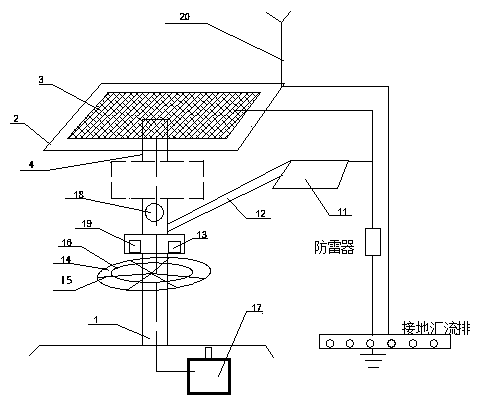
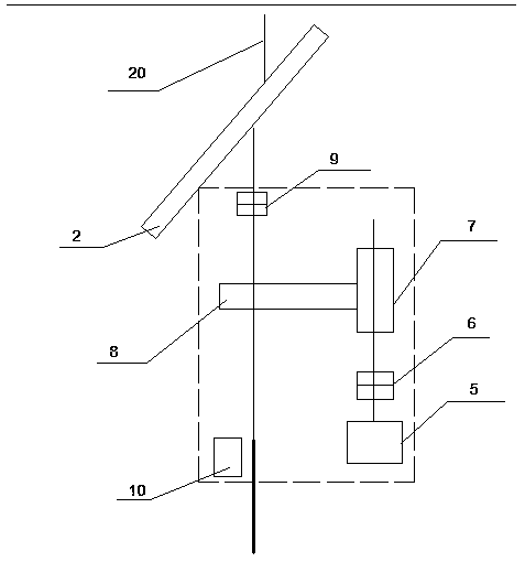
[0021] Embodiment 1: as Figure 1-2 As shown, the solar street light bracket with canopy based on worm gear transmission includes a main support rod 1, and the main support rod 1 is fixed on the ground, and an adjustment device box is fixed above the main support rod 1, and the adjustment device box There is a controller I10 inside, the controller I10 is connected with the stepping motor 5, the output shaft of the stepping motor 5 is connected with the input shaft of the worm 7 through the coupling I6, the worm wheel 8 is installed with the worm 7, and the turbine 8 The output shaft is connected to the lighting support rod 4 through the coupling II9, the lighting support rod 4 is located above the adjustment device box, the top of the lighting support rod 4 is fixed with a support plate 2, and the solar panel 3 is installed on the support plate 2;

[0022] One side of the main support rod 1 is fixed with a street lamp pole 12, the street lamp 11 is installed at the end of the ...

Embodiment 2

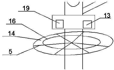
[0026] Embodiment 2: as image 3 As shown, the canopy 14 is umbrella-shaped, the canopy 14 is fixed on the folding rod 15, and the top of the folding rod 15 is fixed on the main support rod 1. Line 16. Described canopy 14 is apart from ground 2m, and stretching diameter is 2m, and its material selects waterproof cloth for use, is also provided with manual switch on canopy 14; The top of the folding rod 15 is fixed on the main support rod 1 by means of buckle; the tightening line 16 is made of a rubber band with certain elasticity. When the rain sensor 18 receives the rain signal, the information is fed back to the controller II 19, the controller II 19 controls the movement of the motor 13, the motor 13 drives the folding rod 15 to drive the canopy 14 to open, and at the same time, the tightening wire 16 relaxes. When the rain sensor 18 fails to receive the rain signal within a period of time, it will feed back the signal to the controller II 19, and the controller II 19 wil...


PUM


Abstract

The invention relates to a solar street lamp bracket with a rain shed based on worm wheel and worm transmission. The solar street lamp bracket is composed of a main supporting rod, a solar power generation device and a sun-shading and rain shielding device, wherein the solar power generation device and the sun and rain shading device are fixed to the main supporting rod. According to the solar street lamp bracket, a controller is utilized to control a stepper motor to drive a worm to conduct transmission, the worm drives a worm wheel to move, the output end of the worm wheel is connected witha daylighting bracket rod, the daylighting bracket rod drives a daylighting bracket and a solar cell panel to move, thus the solar cell panel can roughly move along with the motion trajectory of the sun, and accordingly the power generation capacity of the solar cell panel is increased; meanwhile, a rainwater sensor is used for receiving a rainwater signal, the rain shed in an umbrella shape is arranged on the main supporting rod, the rainwater signal is fed back to the controller, the controller controls the motor to drive a folding rod to be unfolded or folded, and thus the rain shed is unfolded on a rainy day and folded on a sunny day; and the life of people is facilitated greatly.

Description

technical field [0001] The design of the present invention relates to the field of municipal engineering construction, specifically a solar street light bracket with canopy based on turbine and worm drive. Background technique [0002] In recent years, with the development of new energy sources, my country's photovoltaic industry is booming and has become a photovoltaic powerhouse. Photovoltaic power generation projects can be seen everywhere on the road, among which the most common solar street lamp construction on both sides of the road is to install a solar panel on the top of the street lamp bracket, and extend lights of different shapes on the support pole to provide people with nighttime travel. Provides great convenience. However, with the increase of social needs, people's needs are also increasing. The common solar street lamp brackets are fixed, and their power generation efficiency is low. When encountering continuous rain, the power storage capacity is low, whi...

Claims


Application Information

Patent Timeline
Patent Type & Authority Applications(China)
IPC IPC(8): F21S9/03F21V23/00F21V25/00F21V33/00F21W131/103
CPCF21S9/035F21V23/003F21V23/02F21V25/00F21V33/00F21W2131/103Y02B20/72
Inventor 罗小林陈佩霞
Owner KUNMING UNIV OF SCI & TECH
Why Eureka
Try Eureka