

Steam pulse washing device and method
A pulse cleaning and equipment technology, which is applied in washing, lighting and heating equipment, cleaning heat transfer devices, etc., can solve the problem of shortening the service life of plates and rubber pads of plate heat exchangers, increasing the power consumption of circulating water pumps, and consuming manpower and material resources, etc. problems, to achieve the effect of short working hours, reduced cleaning time, and low cost
- Summary
- Abstract
- Description
- Claims
- Application Information
AI Technical Summary
Problems solved by technology
Method used
Image

Examples
Embodiment 1
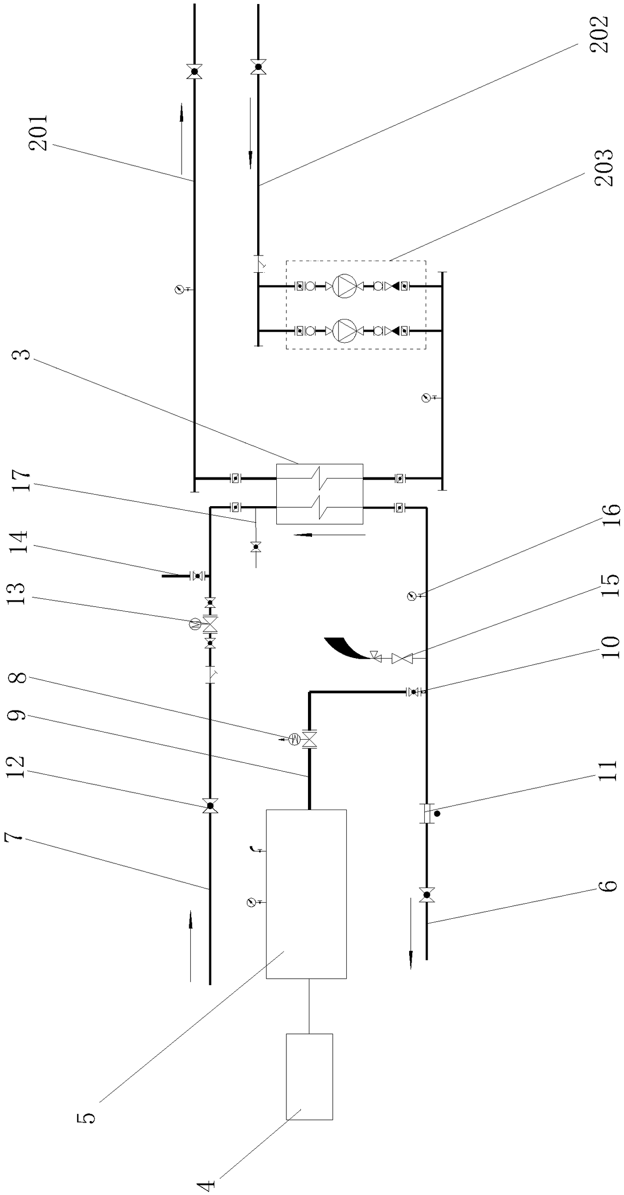
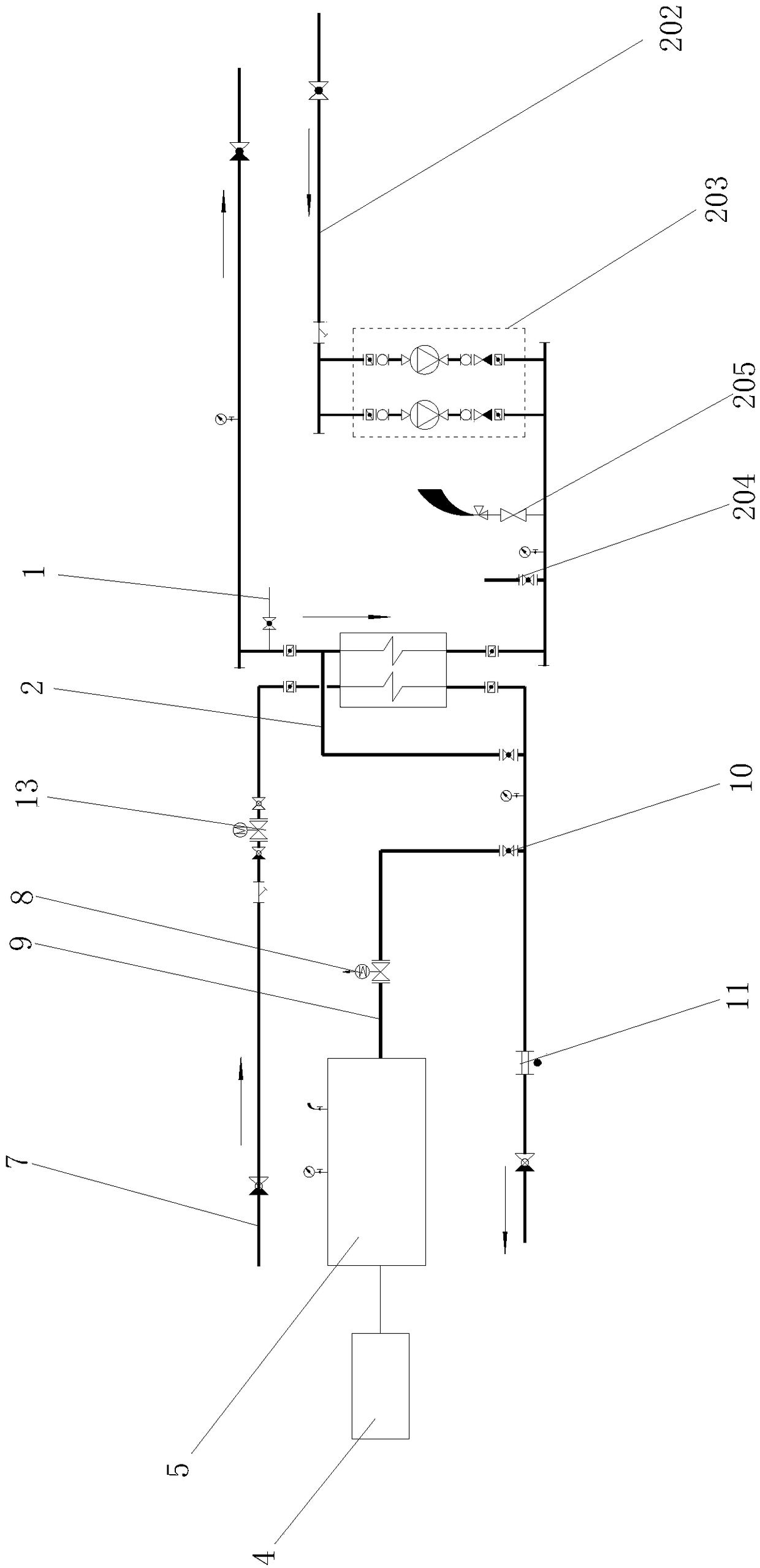
[0033] Embodiment 1: A water-gas pulse cleaning device, including a cleaning device 1, a cleaning device 2 and a plate heat exchanger 3, the cleaning device 1 is connected to the plate heat exchanger 3, and the plate heat exchanger 3 is connected to the cleaning device 2 A flushing pipe 18 is connected between the cleaning device one and the cleaning device two, and the cleaning device one includes an air compressor 4, an air storage tank 5, a first water return pipe 6, a first water supply pipe 7 and a pulse control device 8, and the air compressor 4 is connected to the gas storage tank 5 through pipelines, the gas storage tank 5 is connected to the first return water pipe 6 through the air inlet pipe 9, a port of the first return water pipe 6 is connected to a nozzle of the plate heat exchanger 3, and the first water supply pipe One port of 7 is connected to the other nozzle of the plate heat exchanger 3, the pulse control device 8 is set on the intake pipe 9, the first water...
Embodiment 2
[0035]Embodiment 2: A water-gas pulse cleaning device, including a cleaning device 1, a cleaning device 2 and a plate heat exchanger 3, the cleaning device 1 is connected to the plate heat exchanger 3, and the plate heat exchanger 3 is connected to the cleaning device 2 A flushing pipe 18 is connected between the cleaning device one and the cleaning device two, and the cleaning device one includes an air compressor 4, an air storage tank 5, a first water return pipe 6, a first water supply pipe 7 and a pulse control device 8, and the air compressor 4 is connected to the gas storage tank 5 through pipelines, the gas storage tank 5 is connected to the first return water pipe 6 through the air inlet pipe 9, a port of the first return water pipe 6 is connected to a nozzle of the plate heat exchanger 3, and the first water supply pipe One port of 7 is connected to the other nozzle of the plate heat exchanger 3, the pulse control device 8 is set on the intake pipe 9, the first water ...
Embodiment 3
[0039] Embodiment 3: A water-gas pulse cleaning device, including a cleaning device 1, a cleaning device 2 and a plate heat exchanger 3, the cleaning device 1 is connected to the plate heat exchanger 3, and the plate heat exchanger 3 is connected to the cleaning device 2 A flushing pipe 18 is connected between the cleaning device one and the cleaning device two, and the cleaning device one includes an air compressor 4, an air storage tank 5, a first water return pipe 6, a first water supply pipe 7 and a pulse control device 8, and the air compressor 4 is connected to the gas storage tank 5 through pipelines, the gas storage tank 5 is connected to the first return water pipe 6 through the air inlet pipe 9, a port of the first return water pipe 6 is connected to a nozzle of the plate heat exchanger 3, and the first water supply pipe One port of 7 is connected to the other nozzle of the plate heat exchanger 3, the pulse control device 8 is set on the intake pipe 9, the first water...
PUM
 Abstract
Description
Claims
Application Information