Outer building wall crack detection system and method based on machine vision

A technology for building exterior walls and machine vision, used in instruments, measuring devices, scientific instruments, etc., can solve problems such as large amount of calculation, undisclosed image processing detection methods, and reduced accuracy of kinect depth sensors, so as to improve detection efficiency and reduce The effect of small personal safety risk, improving detection efficiency and detection accuracy

Inactive Publication Date: 2019-01-11
苏州傲特欣智能科技有限公司
View PDF13 Cites 7 Cited by
  • Summary
  • Abstract
  • Description
  • Claims
  • Application Information

AI Technical Summary

Problems solved by technology

[0005] Chinese patent application CN1081195933A discloses a building exterior wall quality defect detection system based on a kinect depth sensor. Through three-dimensional reconstruction of the wall surface, the size measurement and area calculation of defects such as wall cracks, depressions, hollows, etc. are realized, but The accuracy of the kinect depth sensor will be greatly reduced under strong sunlight, and the calculation of the size measurement method through 3D reconstruction is too large
[0006] Chinese patent application CN107202793A discloses a UAV-based building exterior wall quality defect detection system, which detects building exterior wall quality defects by collecting images with visible light and thermal imaging cameras mounted on the UAV, but it is not disclosed Specific image processing and detection methods, and the location of quality defects mainly depends on the GPS system, and the positioning error is large

Method used


Image

  • Outer building wall crack detection system and method based on machine vision
  • Outer building wall crack detection system and method based on machine vision

Examples


Embodiment 1

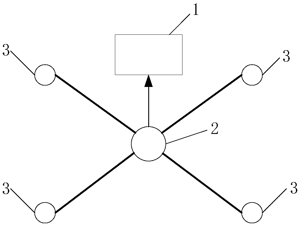
[0036] as attached figure 1As shown, a machine vision-based building exterior wall crack detection system includes a microcomputer processor 1, a CMOS sensor 2 and a laser lighting system 3, the microcomputer processor 1 and the CMOS sensor 2 are connected through a USB interface, and the CMOS sensor 2 and the laser lighting system System 3 is fixedly connected through structural members.

[0037] Microcomputer processor 1 includes core components such as CPU, GPU, memory, and flash memory. Among them, CPU is a quad-core ARM Cortex-A57 processor, GPU is Nvidia Pascal architecture, 256CUDA core, memory is 8GB LPDDR4, flash memory is 32GBeMMC, and runs Linux Ubuntu 16.04 The operating system collects images obtained by the CMOS sensor 2 through USB2.0.

[0038] The laser lighting system 3 includes four point-shaped laser emitters arranged in a rectangle, which can emit four bright laser spots; The center is located at the imaging center of the CMOS sensor 2 .

[0039] The CMO...

Embodiment 2

[0042] as attached figure 1 As shown, based on the above-mentioned embodiment 1, the difference of this embodiment is that the CMOS sensor 2 can collect color images of three channels of red, green and blue, the image resolution is 1280*720 pixels, and the acquisition frame rate is 25 frames per second. Equipped with an 8mm fixed-focus lens, the internal parameter matrix and distortion coefficient of the sensor are obtained through a calibration algorithm before use.

[0043] The laser lighting system 3 is composed of four point-shaped laser emitters arranged in a rectangle, the long side L of the rectangle is 16mm, the short side W is 9mm, the laser wavelength is 710nm, and the power is 2mW. The emitted beam is perpendicular to the imaging plane of the CMOS sensor 2. The center of the rectangle is located at the imaging center of the CMOS sensor 2, and at a distance of 1m, the spot diameter is 2mm; the laser lighting system 3 is fixedly connected to the CMOS sensor 2 through ...

Embodiment 3

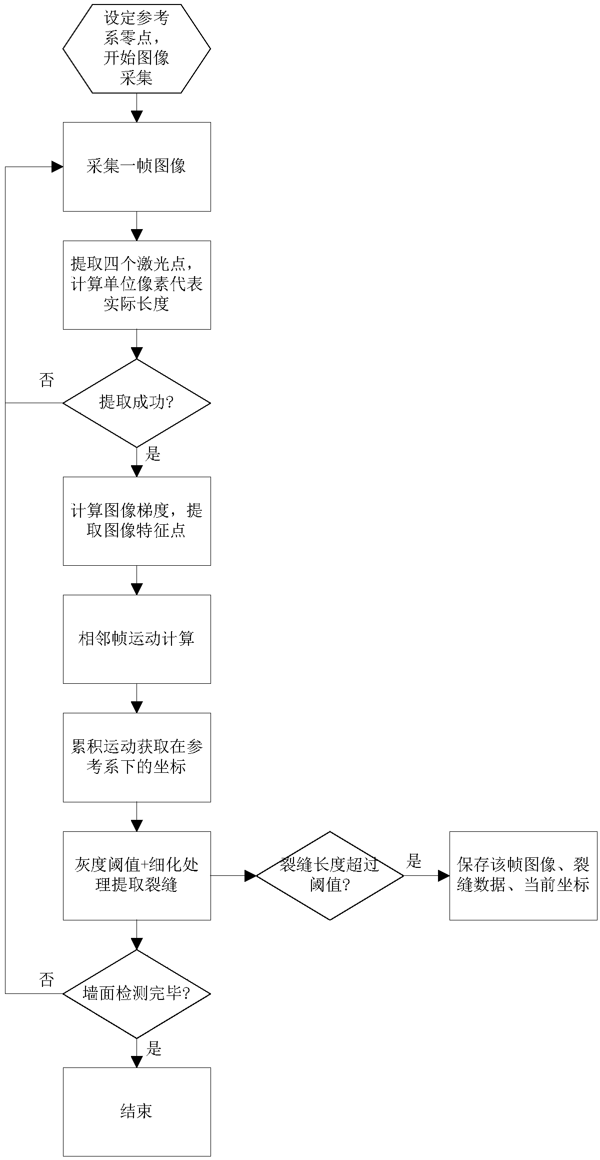
[0047] Based on the foregoing embodiments, a detection method of a machine vision-based building exterior wall crack detection system comprises the following steps:

[0048] (1) Place the CMOS sensor 2 and the laser lighting system 3 parallel to the wall, the longitudinal axis of the imaging plane of the CMOS sensor 2 is vertically downward, and the distance between the CMOS sensor 2 and the outer wall is within 1m, start image acquisition, and ensure four The laser dot is visible within the image;

[0049] (2) Red threshold processing is carried out to image on microcomputer processor 1, extracts four brightest red spots, verifies four vertices that four points form a rectangle, calculates the length Lp and width Wp (in pixels) of rectangle , and then calculate the actual length s=(L+W) / (Lp+Wp) represented by the image unit pixel;

[0050] (3) Taking the current position as the zero point of the building exterior wall reference system, the gradient calculation is carried out...


PUM


Abstract

The invention relates to an outer building wall crack detection system and method based on machine vision. The system comprises a microcomputer processor, a CMOS sensor and a laser illumination system; the laser illumination system comprises four point-like laser transmitters arranged in the form of a rectangle; a transmission light beam is perpendicular to the imaging plane of a CMOS sensor; thecenter of the rectangular is positioned at the imaging center of the CMOS sensor; the microcomputer processor collects the image of the CMOS sensor in real time. According to the method, crack data isextracted via an image gray threshold processing and framework refining algorithm, the actual length corresponding to a unit pixel is acquired according to the pixel length of the rectangular formedby the extracted point-like laser, the absolute position of the current CMOS sensor under an outer wall reference system is acquired according to accumulation of relative movements between two frames,and thus the actual length of a crack and the coordinate of the crack under the outer wall reference system are acquired. According to the outer building wall crack detection system and method basedon machine vision provided by the invention, the automatic detection, size computation and coordinate positioning of the crack can be achieved, and the detection and positioning efficiencies of the crack are greatly improved.

Description

technical field [0001] The invention relates to the technical field of detection of building exterior walls, in particular to a system and method for detecting cracks in building exterior walls based on machine vision. Background technique [0002] With the development of my country's economic and social construction, there are more and more high-rise buildings, and the quality inspection of high-rise buildings has become increasingly important and difficult. As an important part of building quality inspection, the detection of cracks in the exterior walls of high-rise buildings is particularly difficult. On the one hand, high-rise buildings are high and difficult to climb, and manual climbing detection is inefficient and dangerous; on the other hand, cracks often appear irregular, and it is difficult to measure their characteristic data such as width and length. [0003] Machine vision is one of the hottest research topics in the field of automatic inspection. It obtains ...

Claims


Application Information

Patent Timeline
Patent Type & Authority Applications(China)
IPC IPC(8): G01N21/88G01B11/02
CPCG01B11/02G01N21/8851G01N2021/8887
Inventor 杨扬胡心怡顾圣骏
Owner 苏州傲特欣智能科技有限公司
Why Eureka
Try Eureka