Laser radar

A lidar and laser technology, applied in the field of laser detection, can solve problems such as result influence, point cloud and image mismatch, and achieve the effect of reducing difficulty, assembly complexity, and low cost

Inactive Publication Date: 2019-01-11
HESAI TECH CO LTD
View PDF7 Cites 4 Cited by
  • Summary
  • Abstract
  • Description
  • Claims
  • Application Information

AI Technical Summary

Problems solved by technology

[0004] One of the current solutions is to add image sensors such as cameras on the basis of lidar. The problem is that the camera and lidar need to be calibrated
If the calibration is not accurate, or the position between the lidar and the camera deviates during use, there will be a mismatch between the point cloud and the image
And because two sensors are used, both need to be triggered synchronously, if there is an uncertain delay on either side, it will affect the result

Method used


Image

  • Laser radar
  • Laser radar
  • Laser radar

Examples


Embodiment Construction

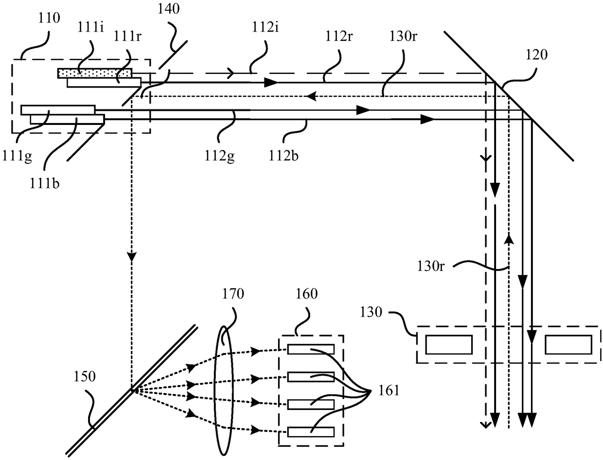
[0033] In order to solve the problem of image matching and synchronous triggering, the existing technology proposes a method to obtain distance information and color information through four lasers and corresponding detectors, including an infrared laser responsible for obtaining distance information, and an infrared laser responsible for obtaining color information. Light, green, blue lasers.

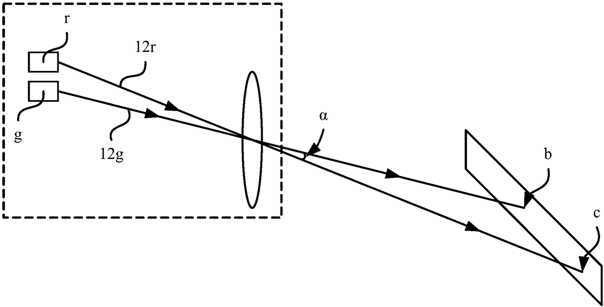
[0034] The lidar includes multiple lasers, and the detection light of the multiple lasers is emitted at a certain divergence angle, so the detection light generated by each laser corresponds to information at different angles. The position where the detection light generated by the laser at different positions is transmitted to the target to be detected will change with the rotation of the laser.

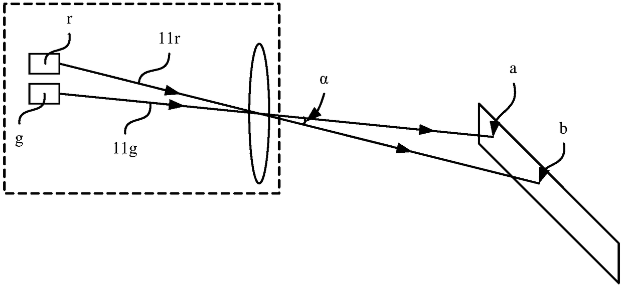
[0035] refer to figure 1 , figure 1 A schematic diagram of part of the optical path of the lidar at time t1 is shown.

[0036] Such as figure 1 As shown, the lidar includes: a first lase...


PUM


Abstract

The invention discloses a laser radar. The laser radar comprises at least one laser emitting unit; the laser emitting unit comprises a plurality of emitting devices; each emitting device generates onepath of detection light; the multiple paths of detection light generated by the emitting devices are emitted in parallel to form an emergent light beam; and the emitting devices include a distance emitting device suitable to generate distance detection light, and a color emitting device suitable to generate color detection light. The laser radar is a color laser radar, and distance information and color information can be obtained at the same time; and the multiple paths of the generated detection light are emitted in parallel, so that the laser radar does not need to calibrate the positionsof different emitting devices, the difficulty of back end data processing can be effectively lowered, and the assembly complexity is lowered; and in addition, the laser radar can realize light beam path sharing without extra optical components, and can meet the development requirements of low cost, miniaturization and solid state.

Description

technical field [0001] The invention relates to the field of laser detection, in particular to a laser radar. Background technique [0002] Lidar is a commonly used ranging sensor, which has the characteristics of long detection distance, high resolution, and low environmental interference. It is widely used in intelligent robots, drones, unmanned driving and other fields. In recent years, with the rapid development of autonomous driving technology, lidar, as the core sensor of distance perception, has become indispensable. [0003] In the current vehicle-mounted lidar, whether it is a lidar with coherent transceiver technology or a lidar based on time-of-flight technology, the feedback signal only contains distance information. If each point can contain color information, it will be more conducive to object recognition. [0004] One of the current solutions is to add image sensors such as cameras on the basis of lidar. The problem is that the camera and lidar need to be c...

Claims


Application Information

Patent Timeline
Patent Type & Authority Applications(China)
IPC IPC(8): G01S7/481
CPCG01S7/4815
Inventor 卢炎聪向少卿
Owner HESAI TECH CO LTD
Why Eureka
Try Eureka