
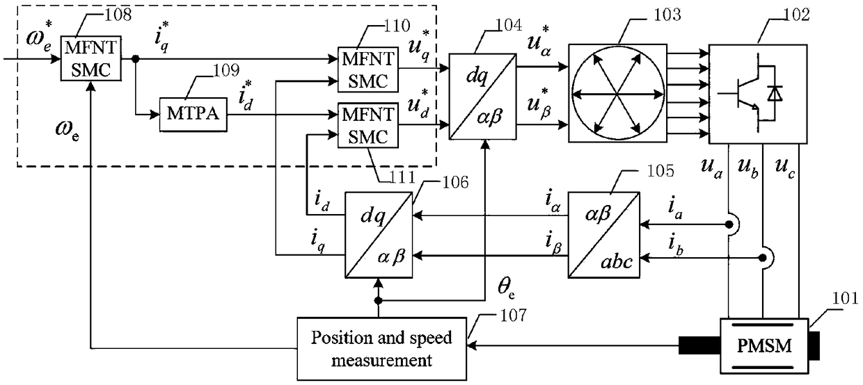
A method and system for sliding mode control of permanent magnet synchronous motor based on model-free and non-singular terminal

A technology for permanent magnet synchronous motors and non-singular terminals, applied in control systems, control generators, vector control systems, etc., can solve problems affecting control performance, model uncertainty, changes in magnetic induction intensity, etc., to achieve efficient and reliable operation , enhance robust performance, and reduce dependencies

Active Publication Date: 2019-01-11
HUNAN UNIV OF TECH
View PDF4 Cites 12 Cited by
  • Summary
  • Abstract
  • Description
  • Claims
  • Application Information

AI Technical Summary

Problems solved by technology

The traditional speed controller and current controller are both PI controllers, which are widely used in motor drive systems due to their simplicity and ease of implementation; however, this type of traditional controller has integral saturation, and the permanent magnet synchronous motor is a non- Linear, strongly coupled system, the system model has uncertainty: In engineering practice, due to the complex and changeable operating conditions of permanent magnet synchronous motors, the stability of permanent magnets will be affected by factors such as temperature and electromagnetics, and the magnetic induction will be Changes will cause the motor to have a demagnetization fault, which will directly affect the control performance of the model-based control method. Traditional controllers are difficult to meet the control requirements of high-performance servo systems
In addition, the parameter error of permanent magnet synchronous motor has a direct impact on the motor control performance. The existing methods such as predictive control with fault-tolerant control function have certain feasibility and effectiveness, but these methods are all model-based control methods, and The model of permanent magnet synchronous motor has uncertainty in some working conditions

Method used


Image

  • A method and system for sliding mode control of permanent magnet synchronous motor based on model-free and non-singular terminal
  • A method and system for sliding mode control of permanent magnet synchronous motor based on model-free and non-singular terminal
  • A method and system for sliding mode control of permanent magnet synchronous motor based on model-free and non-singular terminal

Examples


Embodiment Construction

[0026] The present invention will be further described below in conjunction with specific embodiments.

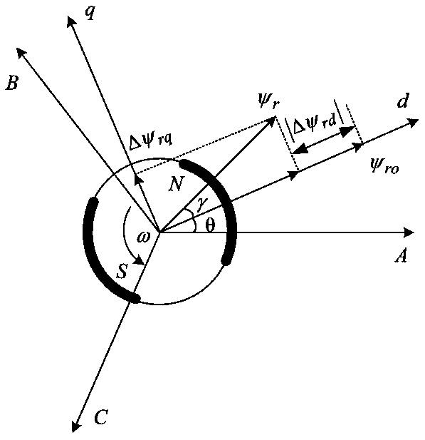
[0027] First, analyze the mathematical models of the permanent magnet synchronous motor under normal conditions and loss of excitation conditions:

[0028] (a) Under normal circumstances

[0029] The voltage equation of the permanent magnet synchronous motor in the d-q coordinate system can be expressed as:

[0030]

[0031] The flux linkage equation of permanent magnet synchronous motor is:

[0032]

[0033] The electromagnetic torque equation of permanent magnet synchronous motor is:

[0034]

[0035] The mechanical motion equation of the permanent magnet synchronous motor is:

[0036]

[0037] In formulas (1)-(4), u d , U q Respectively represent the d-axis and q-axis voltage components; R s Represents stator phase winding resistance; i d , I q Respectively represent the d-axis and q-axis current components; ψ d , Ψ q Respectively represent the d-q axis stator flux linkage component...


PUM


Abstract

A method and system for sliding mode control of permanent magnet synchronous motor based on model-free and non-singular terminal are disclosed in the invention. As compare with that traditional PI controller, the model-free and non-singular terminal sliding mode control method adopt by the invention can reduce the dependency of the controller on the system model, is more suitable for the nonlinearsystem such as the permanent magnet synchronous motor, and simultaneously adopts a sliding mode observer to estimate the unknown quantity, thereby enhancing the robust performance of the method of the invention. The control method of the invention has fast response speed and high control precision, and has certain fault-tolerant control function for permanent magnet loss-of-excitation fault, so that the permanent magnet synchronous motor can run efficiently and reliably under normal conditions or permanent magnet loss-of-excitation conditions.

Description

Technical field [0001] The present invention relates to the technical field of permanent magnet synchronous motors, and more specifically, to a method and system for controlling permanent magnet synchronous motors based on model-free non-singular terminal sliding mode. Background technique [0002] In recent years, permanent magnet synchronous motors have been widely used in rail transit, electric vehicles, aerospace and other fields. People have put forward higher and higher requirements for the control performance of permanent magnet synchronous motor control systems. The traditional speed controllers and current controllers are both PI controllers, which are widely used in motor drive systems due to their simplicity and ease of implementation; however, such traditional controllers have integral saturation, while permanent magnet synchronous motors are a non Linear, strongly coupled system, the model of the system is uncertain: In engineering practice, due to the complicated an...

Claims


Application Information

Patent Timeline
IPC IPC(8): H02P21/00
CPCH02P21/0007H02P2207/05
Inventor 赵凯辉殷童欢张昌凡何静李祥飞陈跃周瑞睿冷傲杰
Owner HUNAN UNIV OF TECH
Learn More