Intelligent control method for plunge milling cutter

An intelligent control and plunge milling technology, which is applied to milling cutters, manufacturing tools, milling machine equipment, etc., can solve the problems of cumbersome operation, single cooling process, and inaccurate temperature measurement, so as to improve machining accuracy, accurate measurement results, and simple operation Effect

Inactive Publication Date: 2019-01-15
HARBIN UNIV OF SCI & TECH
View PDF9 Cites 2 Cited by
  • Summary
  • Abstract
  • Description
  • Claims
  • Application Information

AI Technical Summary

Problems solved by technology

[0010] The present invention aims to solve the problems of cumbersome operation, poor versatility, pollution to the environment, inaccurate temperature measurement, single cooling process, and no joint consideration of temperature and vibration in the existing plunge-milling tool machining process. An intelligent control method for plunge milling cutter

Method used


Image

  • Intelligent control method for plunge milling cutter
  • Intelligent control method for plunge milling cutter
  • Intelligent control method for plunge milling cutter

Examples


specific Embodiment approach 1

[0033] Specific implementation mode one: combine Figure 1 to Figure 4 Describe this embodiment, the intelligent control method of a plunger milling cutter described in this embodiment is realized through the following steps:

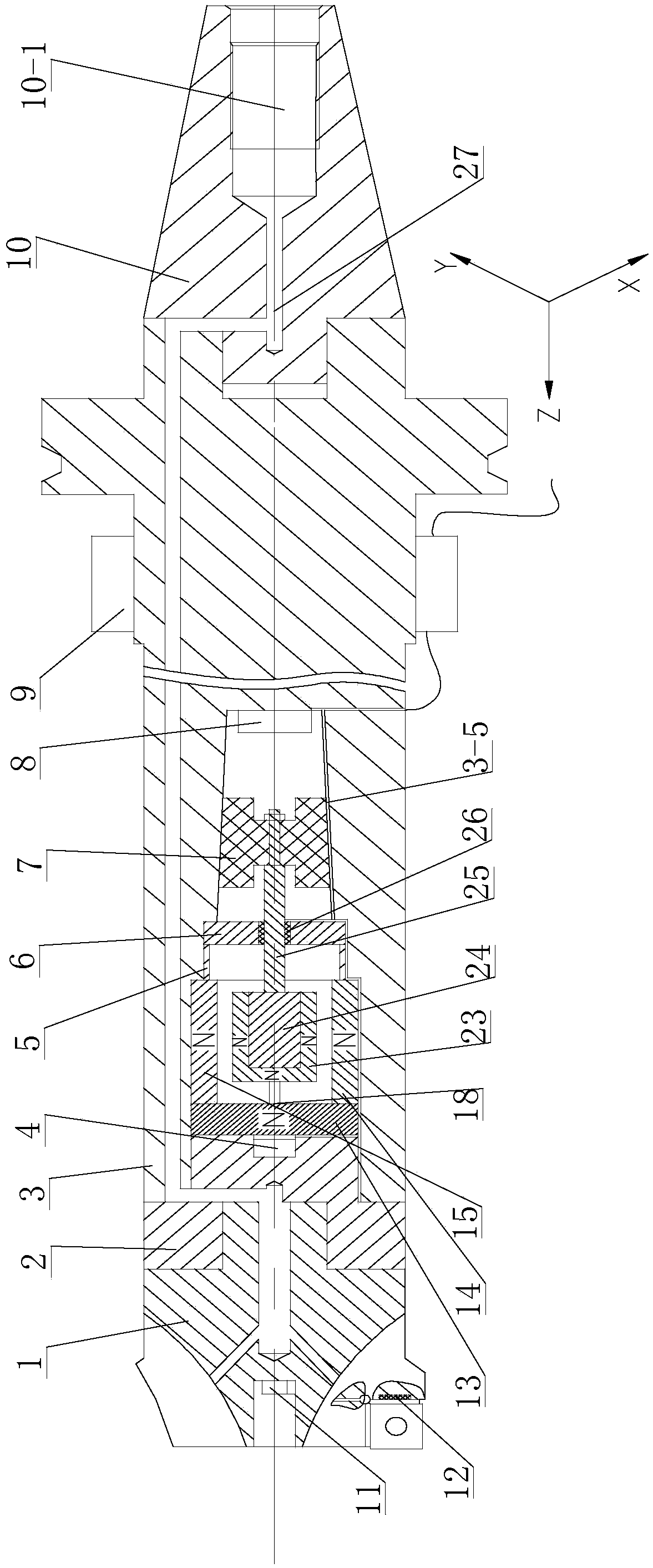
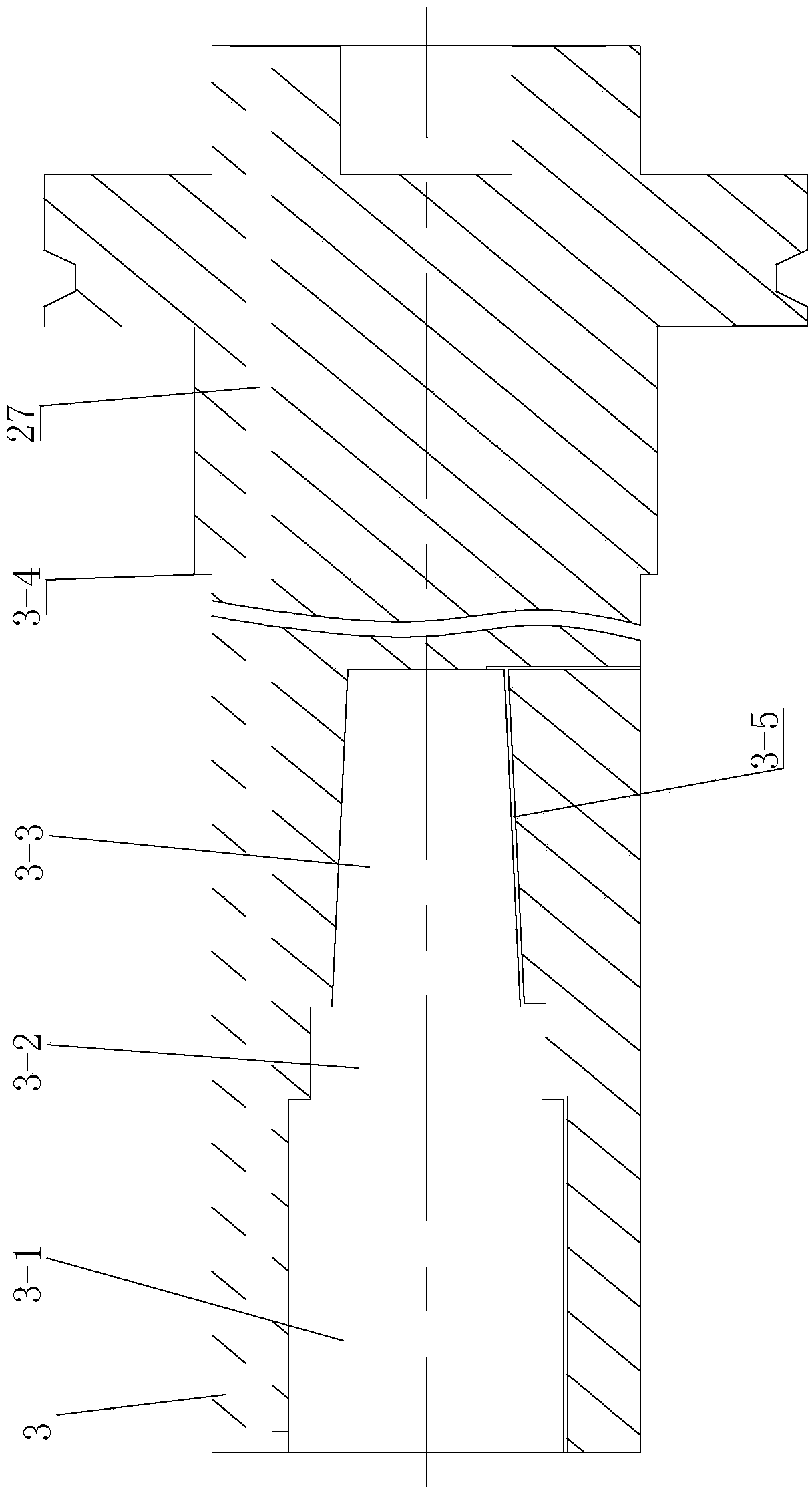
[0034] Step 1. Install the plunge milling cutter; the plunge milling cutter includes a cutter head 1, a cutter head seat 2, a cutter body 3 and a cutter tail seat 10. The cutter head 1 is fixed on the front end of the cutter body 3 through the cutter head seat 2, and the cutter tail seat 10 is fixedly installed on the rear end of the cutter body 3; the plunge milling cutter also includes an acceleration sensor 4, a sleeve 5, a support plate 6, a shock-absorbing rubber 7, a vibration signal controller 8, an electromagnet and a displacement sensor assembly, and a permanent magnet 23. Block 24 and connecting rod 25; First cavity 3-1, second cavity 3-2, third cavity 3-3 are arranged in sequence from front to back in cutter body 3, and acceleration sensor 4 ...

specific Embodiment approach 2

[0037] Specific implementation mode two: combination Figure 1 to Figure 4 To illustrate this embodiment, when the plunge mill itself vibrates in the intelligent control method of the plunge mill described in this embodiment, the control process in step 2 is as follows:

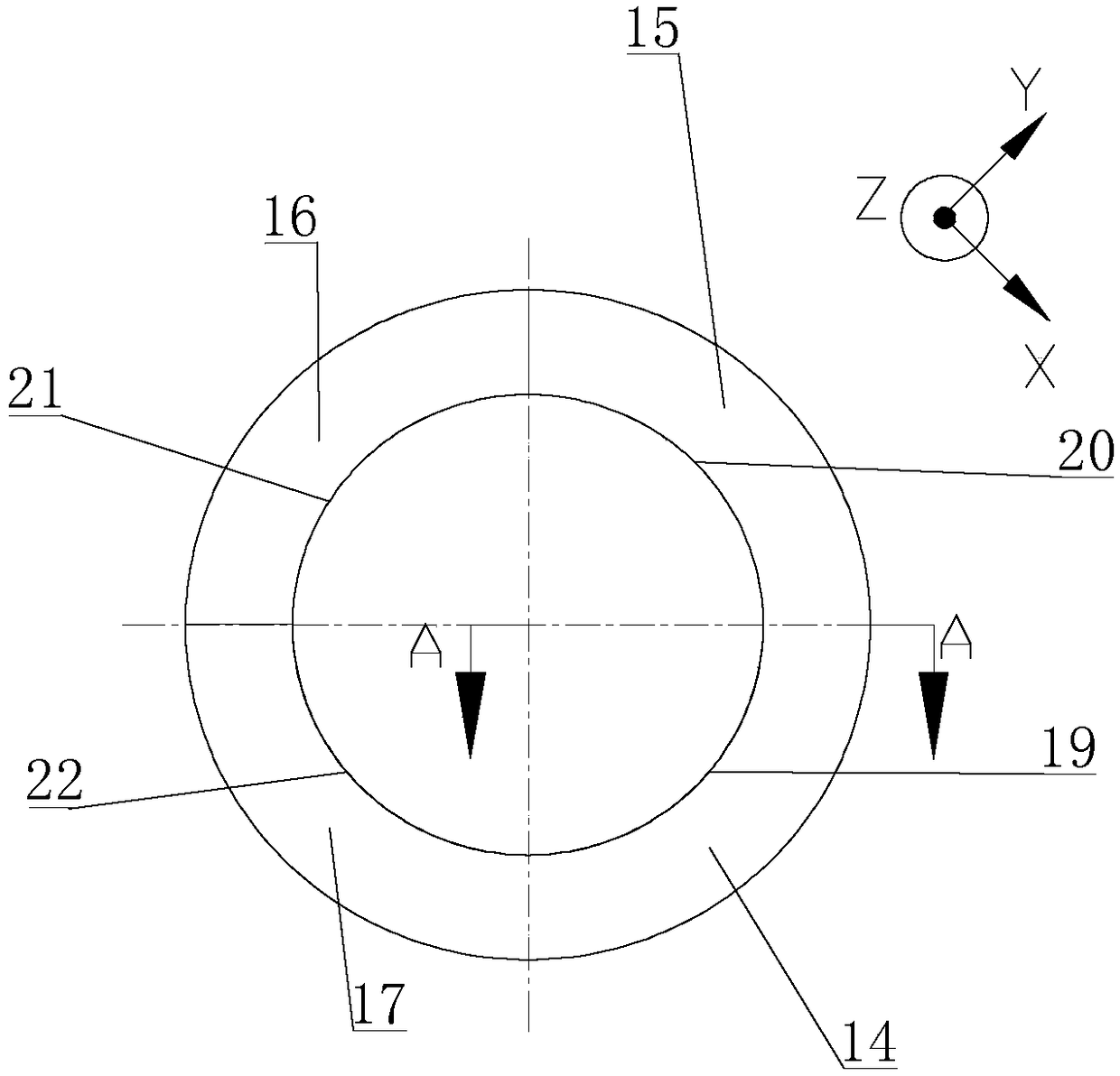
[0038] When the mass block 24 vibrates along the Z positive direction, the No. 1 displacement sensor detects the distance between the mass block 24 and the No. 1 electromagnet. +1 +1 Represent the distance between the current mass block 24 and the No. 1 electromagnet, a represents the preset value, that is, the fixed value distance between the mass block 24 and the electromagnet set in advance in the vibration signal controller 8, and the vibration signal controller 8 controls the current controller Increase the current, increase the repulsive force of the No. 1 electromagnet 13, and then make the mass block 24 away from the No. 1 electromagnet 13. At this time, the No. 2 electromagnet 14, the No. 3 electroma...

specific Embodiment approach 3

[0041] Specific implementation mode three: combination Figure 1 to Figure 3 To illustrate this embodiment, in the intelligent control method for a plunger milling cutter described in this embodiment, after the milling cutter receives external vibrations, the control process in step 2 is as follows:

[0042] After the tool bar is vibrated by the outside world, the acceleration sensor 4 will directly transmit the acceleration signal to the vibration signal controller 8 at the same time. +x When >b, A +x Represents the current X positive acceleration value, b represents the preset value, that is, the positive acceleration value set in advance in the vibration signal controller 8, the vibration signal controller 8 will control the current controller to increase the current, so that the second electromagnet 14 The repulsive force increases, and then makes the mass block 24 away from the second electromagnet 14; when X negative acceleration A -x When >c, A -x Represents the curr...


PUM


Abstract

The invention relates to a control method, in particular to an intelligent control method for a plunge milling cutter. The intelligent control method aims to solve the problems that in the machining process of an existing plunge milling tool, a vibration-damping and cooling control method is complex in operation and poor in universality, pollution is caused to the environment, the temperature measurement is not accurate, the cooling process is single, and the temperature and the vibration are not considered together. The intelligent control method comprises the following steps that the plungemilling cutter is arranged; and an acceleration sensor, a first displacement sensor, a second displacement sensor, a third displacement sensor, a fourth displacement sensor and a fifth displacement sensor transmit detected acceleration signals and displacement signals to a vibration signal controller, the vibration signal controller sends an instruction to a current controller according to the acceleration signals and the displacement signals, and the current controller adjusts currents in a first electromagnet, a second electromagnet, a third electromagnet, a fourth electromagnet and a fifthelectromagnet. The intelligent control method belongs to the field of machining.

Description

technical field [0001] The invention relates to a control method, in particular to an intelligent control method for a plunge milling cutter, which belongs to the field of mechanical processing. Background technique [0002] As the mainstream milling method in mechanical processing, plunge milling has the advantages of high metal removal efficiency and high processing quality, and is widely used. However, when processing the root of the water bucket of a power generation turbine, it is necessary to use a slender shape of the tool holder. The increase of the length-to-diameter ratio will inevitably produce obvious flutter, and it is difficult to achieve high-precision machining. In addition, the amount of metal removal is not constant during the processing of the water bucket, which will inevitably lead to constant changes in the vibration frequency of the cutter bar. , so there is a need for an intelligent tool holder that can automatically adjust according to different cutt...

Claims


Application Information

Patent Timeline
Patent Type & Authority Applications(China)
IPC IPC(8): B23C5/00B23Q17/00B23Q17/12
CPCB23C5/00B23C5/003B23Q17/00B23Q17/12
Inventor 王宇盖竹兴翟元盛卢佳鹤
Owner HARBIN UNIV OF SCI & TECH
Why Eureka
Try Eureka