
Steel pipe-concrete pile foundation as temporary foundation and construction method thereof

A technology of concrete piles and steel pipes, applied in infrastructure engineering, architecture, bridge construction, etc., can solve the problems of unsuitable flyover bridges, increased construction costs, and large construction work areas, so as to shorten the construction period and reduce waste of resources , The effect of groundwater level is small

Inactive Publication Date: 2019-01-15
SHANDONG JIAOTONG UNIV
View PDF0 Cites 2 Cited by
  • Summary
  • Abstract
  • Description
  • Claims
  • Application Information

AI Technical Summary

Problems solved by technology

However, during the construction and implementation of these two types of foundations, large-scale machinery is usually required to drill holes. There are problems such as large construction work areas and a large number of equipment. It is not suitable for flyover bridges with narrow work areas.
At the same time, if this kind of foundation is used as the temporary foundation of the flyover bridge, it will easily cause a lot of waste of resources, increase the construction cost, and is not conducive to the control of the construction period
Existing steel pipe pile foundations are often used in temporary support structures, but their bearing capacity is low and their stability is poor, which cannot meet the requirements of higher bearing capacity for bridge construction temporary structures

Method used


Image

  • Steel pipe-concrete pile foundation as temporary foundation and construction method thereof
  • Steel pipe-concrete pile foundation as temporary foundation and construction method thereof
  • Steel pipe-concrete pile foundation as temporary foundation and construction method thereof

Examples


Embodiment Construction

[0057] The present invention will be further described below in conjunction with the accompanying drawings and embodiments.

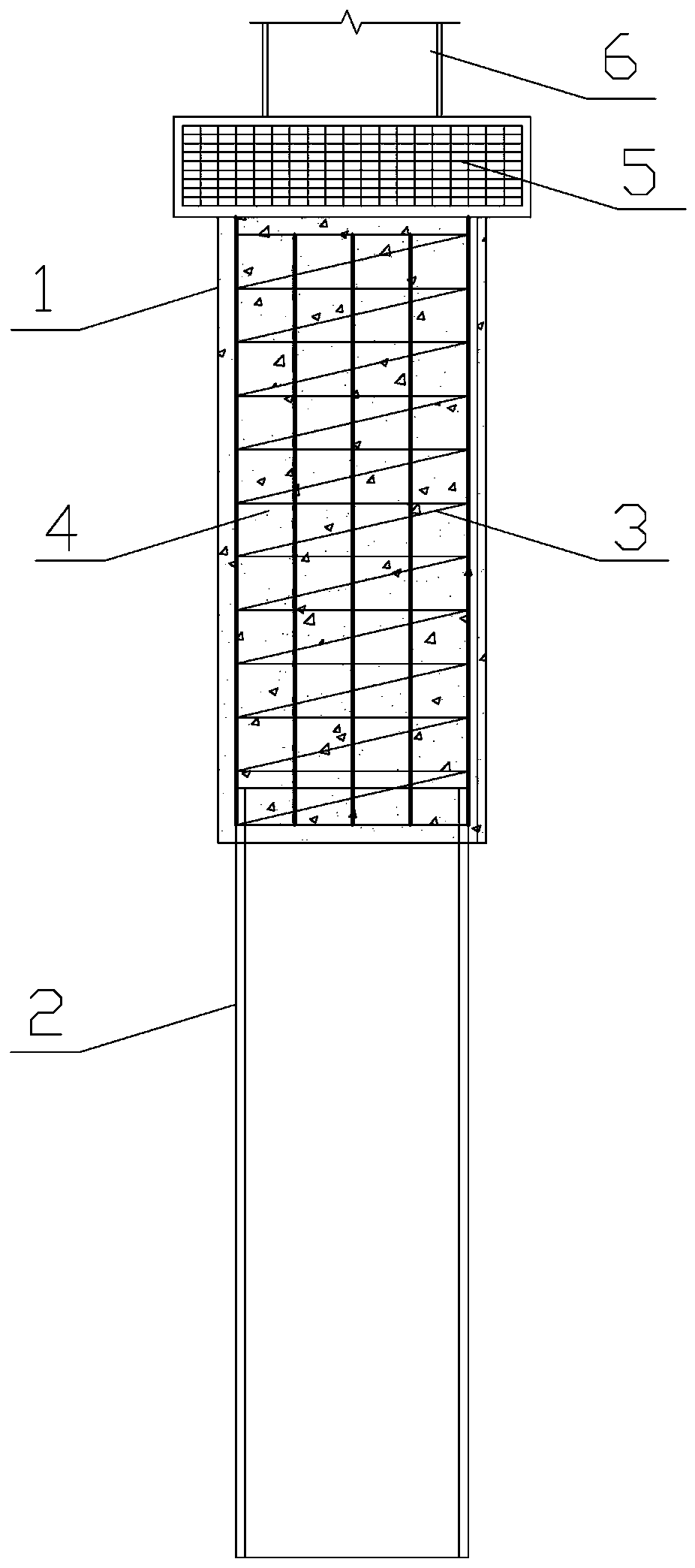
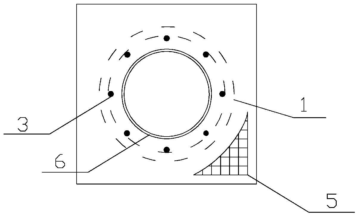
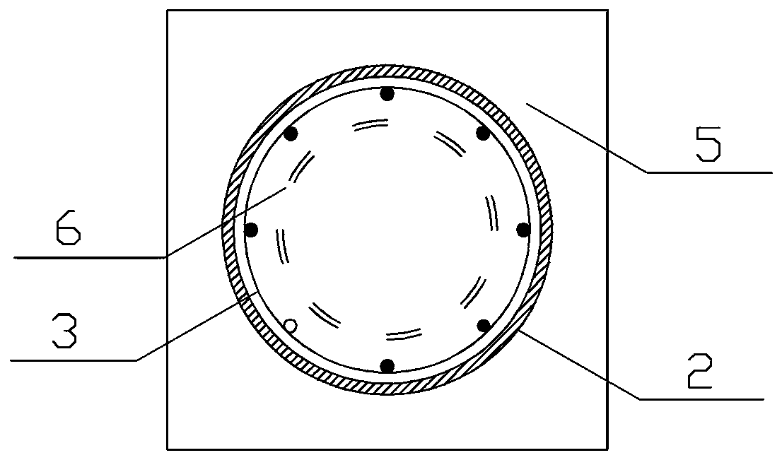
[0058] Such as figure 1 , figure 2 and image 3 As shown, the front view, top view and bottom view of the steel pipe-concrete pile foundation as a temporary foundation of the present invention are respectively provided, which are composed of hole piles 1, steel pipes 2, caps 5 and steel pipe column temporary piers 6, as shown The hole pile 1 is composed of a steel cage 3 and concrete 4, the steel pipe 2 is located under the hole pile 1, the steel pipe 2 and the hole pile 1 are in a vertical state, and the steel pipe 2 and the hole pile 1 are coaxially arranged. The hole pile 1 is formed in the pile hole 1 dug by the workers in layers, the upper end of the steel pipe 2 extends into the bottom of the pile hole, and the lower part of the reinforcement cage 3 is welded together with the overlapping part of the upper end of the steel pipe 2 to realize the...


PUM


Abstract

A steel pipe-concrete pile foundation as a temporary foundation of the invention comprises a hole pile, a steel pipe, a cushion cap and a steel pipe column temporary pier, wherein the hole pile and the steel pipe are all located in the foundation, the steel pipe is located below the hole pile, the hole pile is composed of a steel cage and concrete. The upper end of the steel pipe is fixed to the lower end of the steel cage, the cushion cap is fixed to the upper end of the hole pile, and the steel pipe column temporary pier is fixed on the cushion cap. The method for constructing a pile foundation of the present invention comprises the steps of a), exporting soil; b), determining the depth of the hole digging and the entering depth of soil; c), marking a construction site; d), digging a pile hole in sections; e), driving in the steel pipe; f), cutting the steel pipe; g), welding the steel cage; h), pouring concrete; i), constructing the cushion cap; and j), setting a temporary pier. Thesteel pipe-concrete pile foundation of the invention combines a steel pipe pile and a hole pile, and is suitable for constructing a temporary pier foundation in a narrow working space across an existing railway and highway environment. The steel pipe-concrete pile foundation has outstanding beneficial effects and is suitable for application and promotion.

Description

technical field [0001] The invention relates to a pier as a temporary foundation, more specifically, to a steel pipe-concrete pile foundation as a temporary foundation and a construction method thereof. Background technique [0002] In bridge construction, it often encounters the construction environment of crossing existing railway lines and highways. In the construction of bridge spans, the superstructure is often put in place by the jacking method. As a transitional temporary pier foundation, it is a crucial component in the process of jacking construction of long-span bridges. However, in many cases, the construction environment of cross-line bridges is complex. When building temporary pier foundations between multiple existing railway lines, the construction work space is limited and the groundwater level is limited, resulting in limited use or even inability to use large-scale equipment. Organizing the construction makes the construction more difficult; or affected by...

Claims


Application Information

Patent Timeline
IPC IPC(8): E02D27/12E01D21/00
CPCE02D27/12E01D21/00
Inventor 李晋张小宁崔凤坤崔新壮董旭左珅
Owner SHANDONG JIAOTONG UNIV
Learn More