
Support structure and construction method of cantilever plate for house building project

A supporting structure and cantilevered slab technology, which is applied to building structures, on-site preparation of building components, pillars, etc., can solve problems such as bolt loosening, steel frame support structure wall movement, and influence on cantilever slab pouring, etc. Achieve the effects of preventing detachment, facilitating pouring, and reducing occupied space

Inactive Publication Date: 2019-01-15
深圳市鹏升建设有限公司
View PDF7 Cites 17 Cited by
  • Summary
  • Abstract
  • Description
  • Claims
  • Application Information

AI Technical Summary

Problems solved by technology

[0004] In the above-mentioned existing technical solutions, the beams, columns, and diagonal braces are welded into triangular supports, and then fixedly connected by bolts to ensure the safety of disassembly and assembly. However, this structure uses bolts to complete the wall and steel frame support structure. Fixed, the bolts are easy to loosen, which will cause the steel frame support structure to move relative to the wall and affect the pouring of the cantilever slab

Method used


Image

  • Support structure and construction method of cantilever plate for house building project
  • Support structure and construction method of cantilever plate for house building project
  • Support structure and construction method of cantilever plate for house building project

Examples


Embodiment 2

[0058] Embodiment 2: A construction method of a cantilevered slab for house construction, comprising the following steps:

[0059] Step 1, planting the wall screw 1, including the following steps:

[0060] 1. Positioning: Mark the drilling marks according to the design requirements. If there are stressed steel bars on the wall, the drilling positions can be adjusted appropriately, but they should be planted inside the stirrups or inside the step-by-step bars;

[0061] 2. Drilling: Use an electric hammer or air drill to form a hole. If the steel bar is encountered, adjust the hole position to avoid it. If a drilling machine is used to form a hole, the debris in the drilled hole should be rinsed with crystal water and dried in the sun;

[0062]3. Hole cleaning: After drilling, check the depth and diameter of the hole. After passing the test, blow out the dust in the hole with compressed air, then use a brush to clean the hole wall, and then blow it out with compressed air again....


PUM


Abstract

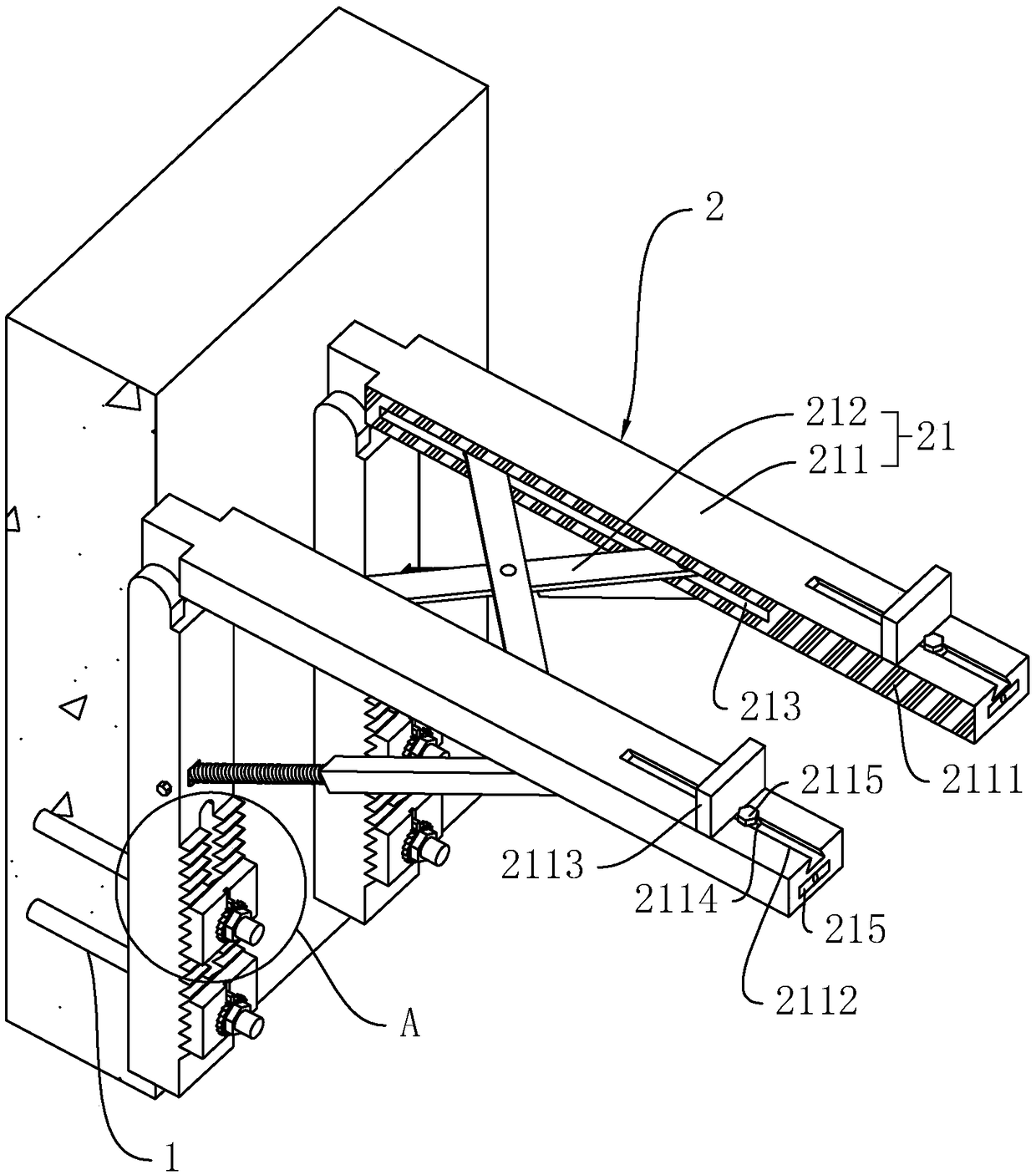
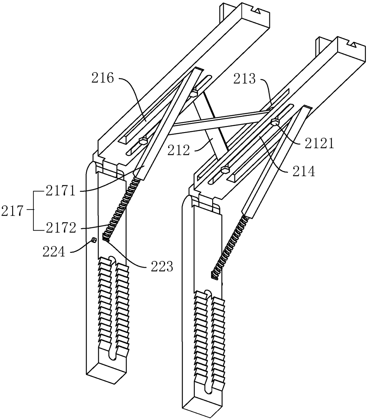
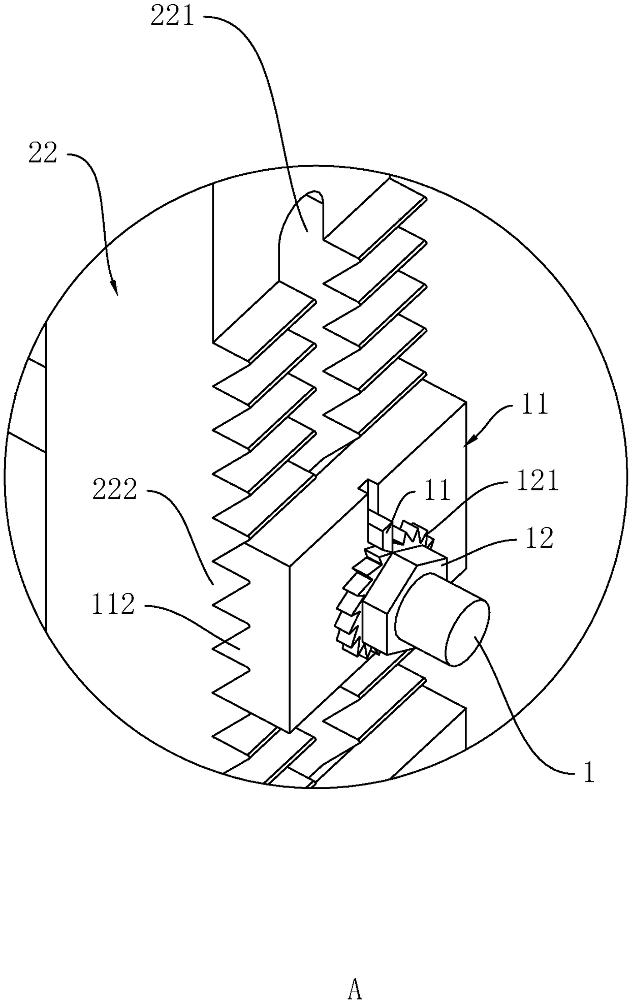
The invention relates to a support structure and a construction method of a cantilever plate for a house building project, and belongs to the field of cantilever plate construction. The support structure comprises wall-through screws and a bracing frame, the bracing frame comprises a carrying rack arranged horizontally and two fixed rods arranged vertically, the upper ends of the fixed rods are connected to the carrying rack, the side, far from the wall, of each fixed rod is vertically provided with a chute, the fixed rod is fixedly provided with ratchet bars at positions corresponding to thetwo sides of the chute, one end of each wall-through screw penetrates the chute, the fixed rod is provided with fixed plates corresponding to the ends, penetrating the chutes, of the wall-through screws, the side, far from the wall, of each fixed plate is in transmission connection with a nut which is in threaded connection with a screw, the circumference of the nut is fixedly connected with a ratchet ring, position, corresponding to the upper of the ratchet ring, of the fixed plate is in vertically sliding connection with a ratchet, and the side, close to the wall, of the fixed plate is provided with a ratchet plate whose tooth direction is opposite with that of the ratchet bar. The height of the support structure is convenient to adjust, and the bracing frame is firmly fixed to the wall.

Description

technical field [0001] The invention relates to the field of cantilevered slab construction, in particular to a support structure of a cantilevered slab used in house construction and a construction method thereof. Background technique [0002] Cantilever structures are widely used in buildings, such as cantilevered eaves, balconies, stadium stands, station platforms, and theater platforms. With the rapid development of technology, in contemporary architecture, the scale of cantilever is getting bigger and bigger, and there are more and more ways of application, and it is also playing an increasingly important role in the creation of architectural expression. The cantilevered slab is only supported on one side, its main stress bars are placed above the slab, and the distributed steel bars are placed below the main stress bars. Different from the bending moment at the end, the thickness of the end of the cantilever slab is smaller than that of the root. [0003] You can ref...

Claims


Application Information

Patent Timeline
Patent Type & Authority Applications(China)
IPC IPC(8): E04B1/00E04G13/06E04G25/00
CPCE04B1/00E04G13/06E04G25/00
Inventor 纪楚辉
Owner 深圳市鹏升建设有限公司
Learn More