Sealing technique for restraining leakage flow loss of back cavity of centripetal turbine

A leakage flow and back technology, applied in the direction of leakage prevention, engine components, machines/engines, etc., can solve unconsidered problems, achieve the effect of improving utilization efficiency, strong adaptability, and easy maintenance and replacement

Active Publication Date: 2019-01-15
INST OF ENGINEERING THERMOPHYSICS - CHINESE ACAD OF SCI
View PDF9 Cites 9 Cited by
  • Summary
  • Abstract
  • Description
  • Claims
  • Application Information

AI Technical Summary

Problems solved by technology

However, this method does not take into account the leakage of the working medium in the back cavity 50 of the upstream wheel disc of the grate tooth seal structure 60 to the main channel of the impeller driven by the centrifugal force of the high-speed rotation of the impeller, and the relationship between the working medium in the main channel of the impeller and the high-entropy working medium in this area. Flow losses due to mass and energy exchange of

Method used


Image

  • Sealing technique for restraining leakage flow loss of back cavity of centripetal turbine
  • Sealing technique for restraining leakage flow loss of back cavity of centripetal turbine
  • Sealing technique for restraining leakage flow loss of back cavity of centripetal turbine

Examples


Embodiment Construction

[0025] In order to make the object, technical solution and advantages of the present invention clearer, the present invention will be further described in detail below with reference to the accompanying drawings and examples.

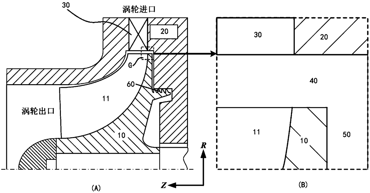
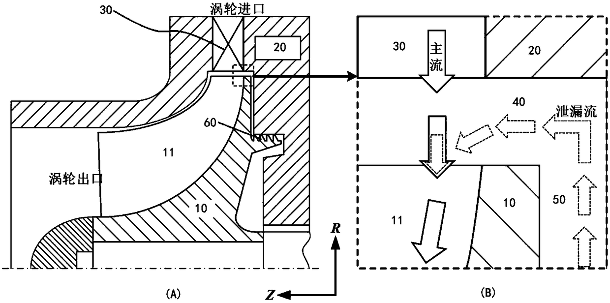
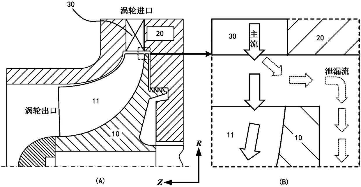
[0026] Such as Figure 4 As shown, the structure for suppressing the leakage flow loss of the back cavity of the centripetal turbine impeller of the present invention is used to suppress the leakage movement of the fluid from the back cavity of the impeller to the main channel of the impeller. The centripetal turbine includes an impeller 10 and a casing 20. The surface of the impeller 10 is uniformly distributed with a plurality of blades along its circumference. There is a tip gap 40 between the top of the impeller 10 and the casing 20. The impeller back cavity 50 is formed between them, and the wheel top gap 40 communicates with the impeller back cavity 50. The middle radial position of the impeller back is provided with a grate tooth 60 and forms a g...


PUM


Abstract

The invention discloses a sealing technique for restraining the leakage flow loss of a back cavity of a centripetal turbine. According to the specific structure, a leakage flow sealing structure is arranged on a case in a junction area of a main passage of the centripetal turbine and the back cavity of an impeller, wherein the sealing structure can be in a rectangular protrusion form or a trapezoidal protrusion form or is a comb tooth sealing structure, a brush-type sealing structure or the like and can be made from soft metal, graphite or other materials so as to reduce abrasion to the impeller; the sealing structure can be disassembled from the case so as to be replaced after being abraded; and the sealing structure can be applied to centripetal turbines in multiple fields such as aerospace, transportation and compressed air energy storage and is particularly suitable for high-pressure centripetal turbines. The sealing structure has the advantages that leakage of working medium gas to the back cavity of the impeller from an impeller passage and leakage of sealing gas in the back cavity of the impeller to the impeller passage are effectively controlled, so that the leakage flow loss of the back cavity of the impeller of the centripetal turbine is effectively controlled, the pneumatic efficiency of the centripetal turbine is improved, the energy utilization rate is increased, and maintenance and replacement are facilitated.

Description

technical field [0001] The invention relates to the technical field of centripetal turbines in turbomachinery, and relates to a technology for controlling internal leakage flow loss of a centripetal turbine, in particular to a sealing technology for suppressing leakage loss in the back cavity of a centripetal turbine. Background technique [0002] The impeller machinery is widely used and has a variety of structural types, providing electricity and power for industrial production and public life in various fields. As a type of impeller machinery, the centripetal turbine has the characteristics of simple structure, low cost, and high single-stage pressure ratio, and has been widely used. In order to make a unit volume of equipment output as much mechanical energy as possible under the same thermal parameters, it is necessary to improve the efficiency of the centripetal turbine. Such as Figure 1~3 As shown, due to the rotation of the impeller 10 of the centripetal turbine, t...

Claims


Application Information

Patent Timeline
Patent Type & Authority Applications(China)
IPC IPC(8): F01D11/08F01D11/10F01D25/24
CPCF01D11/08F01D11/10F01D25/24Y02E10/20
Inventor 王星陈海生张雪辉李文朱阳历
Owner INST OF ENGINEERING THERMOPHYSICS - CHINESE ACAD OF SCI
Why Eureka
Try Eureka