Variable heat energy recovery system and method for cogeneration unit

A cogeneration unit and heat energy recovery technology, applied in mechanical equipment, steam engine devices, engine components, etc., can solve the problems of application scenarios and small market volume, and achieve the effect of ensuring normal operation, saving costs, and reducing investment.

Active Publication Date: 2021-08-17
ENN SCI & TECH DEV +1
View PDF5 Cites 0 Cited by
  • Summary
  • Abstract
  • Description
  • Claims
  • Application Information

AI Technical Summary

Problems solved by technology

[0004] For this reason, the technical problem to be solved by the present invention is to overcome the problems in the prior art that the recovered heat is fixed and the application scenarios and market volume are small, so as to provide a controllable recovery of heat energy, reduce the investment of the peripheral heat storage system, and meet the needs of customers. Variable heat energy recovery system and method for cogeneration units with different heat demands

Method used


Image

  • Variable heat energy recovery system and method for cogeneration unit

Examples


Embodiment 1

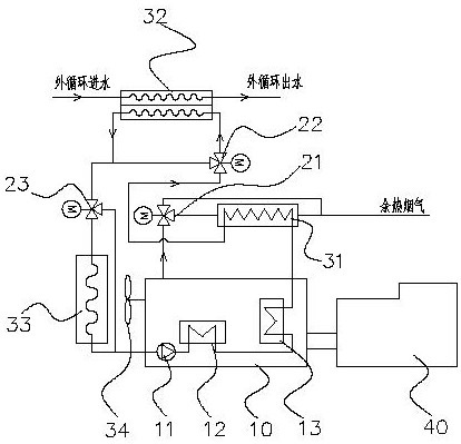
[0021] like figure 1 As shown, the present embodiment provides a variable heat energy recovery system for cogeneration units, including a gas internal combustion engine 10, a water pump 11, a cooler 12 connected to the water pump 11, and a cooling system connected to the gas internal combustion engine 10 are provided. The cylinder liner 13 connected with the device 12, the exhaust port of the gas internal combustion engine 10 is connected with the first channel inlet end of the first heat exchanger 31 through the first valve 21, and the cylinder liner 13 is connected with the first heat exchanger 31 is connected to the second passage inlet end of the first heat exchanger 31, and the second passage outlet end of the first heat exchanger 31 is connected to the first passage inlet end of the second heat exchanger 32 through the second valve 22, and the second valve 22 is connected to the first passage inlet end of the second heat exchanger 32. The third valve 23 is connected, the...

Embodiment 2

[0033] This embodiment provides a method for recovering variable heat energy of a combined heat and power unit. According to the variable heat energy recovery system of a cogeneration unit described in Embodiment 1, the controllable recovery of energy includes the following steps: Step S1: Control the first valve 21, the first heat exchange is performed on the internal circulating fluid of the gas internal combustion engine 10; Step S2: Control the opening of the second valve 22, and perform a second heat exchange on the internal circulating fluid after the first heat exchange or Avoid performing a second heat exchange on the internal circulating fluid after the first heat exchange; Step S3: Control the opening of the third valve 23, and transport the internal circulating fluid after the second heat exchange to the gas internal combustion engine 10, Return to step S1 until the second heat exchange is performed on the internal circulating fluid after the first heat exchange in s...


PUM


Abstract

The invention relates to a system and method for recovering variable heat energy of a cogeneration unit, comprising a gas internal combustion engine, the gas internal combustion engine is provided with a water pump, a cooler, and a cylinder liner, and the exhaust port of the gas internal combustion engine passes through a first valve and a second valve. The inlet end of the first passage of a heat exchanger is connected, the cylinder liner is connected with the inlet end of the second passage of the first heat exchanger, and the outlet end of the second passage of the first heat exchanger is connected to the second passage through the second valve. The inlet end of the first passage of the second heat exchanger is connected, the second valve is connected with the third valve, the outlet end of the first passage of the second heat exchanger is connected with the third valve, and the third valve The first radiator is connected to the water pump, and the heat recovered by the first heat exchanger and the heat exchanged by the second heat exchanger are controlled according to the opening degrees of the first valve, the second valve and the third valve. . The invention can meet the needs of customers for different heat.

Description

technical field [0001] The invention relates to the technical field of heat and power cogeneration, in particular to a system and method for recovering variable heat energy of a heat and power cogeneration unit. Background technique [0002] The gas cogeneration system is a new type of energy system, which mainly uses combustible gases such as natural gas, biogas or coal bed methane to burn and generate power, and recovers the waste heat after combustion to be used for cooling, heating, hot water or steam production . Compared with conventional energy supply systems, it has the advantages of high comprehensive efficiency, energy saving and environmental protection, safety and reliability, and good economy. [0003] With the advancement of energy utilization technology, gas-fired combined cooling, heating and power systems are being used more and more due to their proximity to customers, low loss, high comprehensive energy efficiency, and energy supply security. At present,...

Claims


Application Information

Patent Timeline
Patent Type & Authority Patents(China)
IPC IPC(8): F01K23/10F01K27/00F02G5/02F01K21/00
CPCF01K21/00F01K23/10F01K27/00F02G5/02Y02E20/14Y02T10/12
Inventor 李永志武海滨郑文学
Owner ENN SCI & TECH DEV
Why Eureka
Try Eureka