
Pulse detonation pushing device based on regenerative cooling structure

A technology of regenerative cooling and pulse detonation, which is applied to jet propulsion devices, intermittent jet devices, rocket engine devices, etc., can solve the problems of inability to solve the cooling problem of hot-end components, thermal protection of hot-end components, and long detonation time. Achieve improved overall propulsion performance, fast blending, low quality and low hazard

Inactive Publication Date: 2019-01-15
NORTHWESTERN POLYTECHNICAL UNIV
View PDF5 Cites 10 Cited by
  • Summary
  • Abstract
  • Description
  • Claims
  • Application Information

AI Technical Summary

Problems solved by technology

When liquid fuel is used, the flue gas temperature after detonation combustion exceeds 3500K. At this time, each part in the detonation tube bears a huge heat load, and the traditional cooling method can no longer solve the cooling problem of the hot end parts.
[0005] In view of the above problems, in order to achieve high-performance and stable operation of the detonation engine using liquid fuel, a new pulse detonation engine detonation tube structure must be designed to solve the problem of long detonation time, long detonation distance and thermal protection of hot-end components during the working process. The problem

Method used


Image

  • Pulse detonation pushing device based on regenerative cooling structure
  • Pulse detonation pushing device based on regenerative cooling structure
  • Pulse detonation pushing device based on regenerative cooling structure

Examples


Embodiment Construction

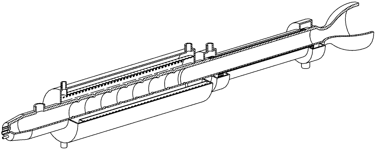
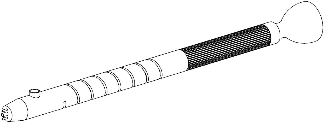
[0036] The present invention will be further described in detail below in conjunction with the accompanying drawings.

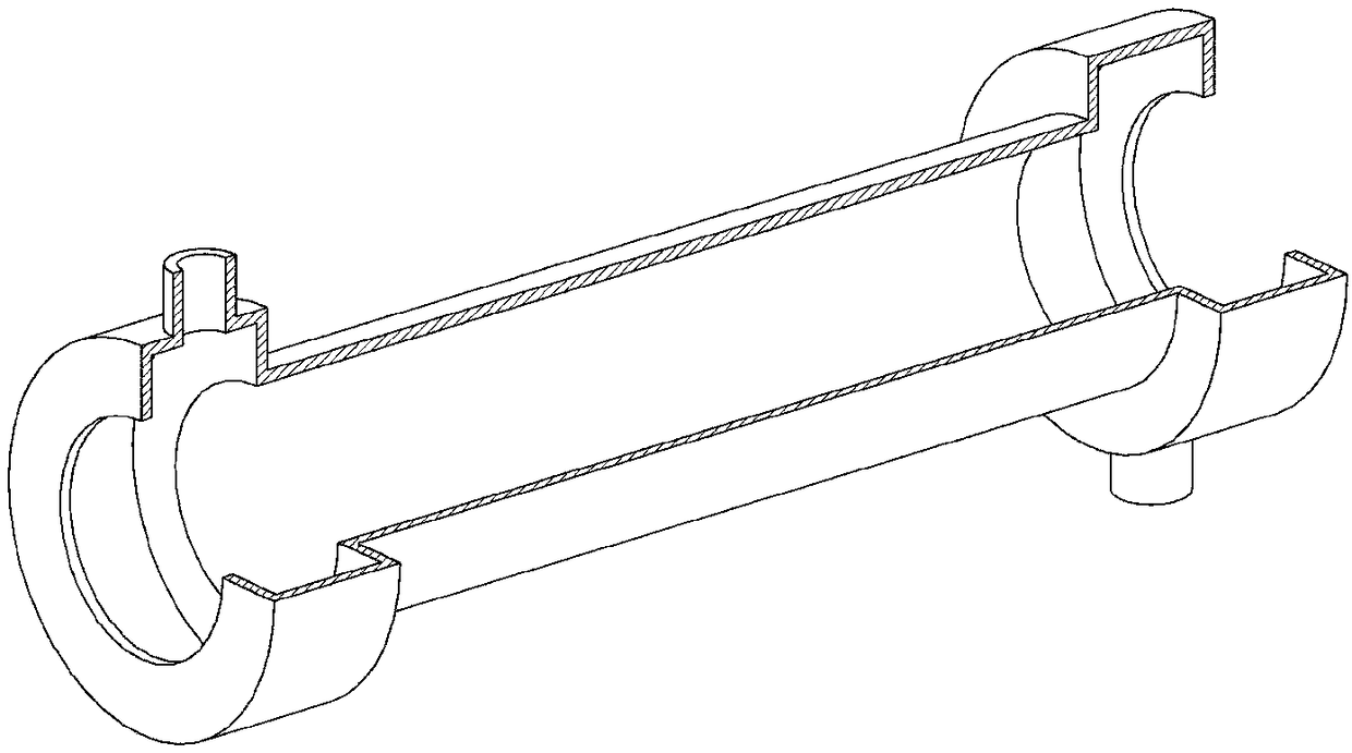
[0037] The present invention is a propulsion structure for a regeneratively cooled pulse detonation engine, such as Figure 5 with Image 6 shown. It includes: detonation tube 1, head 1-1, DDT section 1-2, detonation propagation section 1-3, igniter interface 1-4, Shchelkin spiral obstacle 1-5, heat exchange microchannel 1-6 , fuel inlet 1-7, oxidant inlet 1-8, second stage heater 2, second stage heater fuel inlet 2-1, second stage heater fuel outlet 2-2, partition 3 with impact holes , impact hole 3-1, first stage preheater 4, liquid collection chamber 4-1, first stage preheater fuel inlet 4-2, first stage preheater fuel outlet 4-3, fuel pipeline 5 , oxidant pipeline 6 and igniter 7.

[0038] The propulsion structure of a regenerative cooling pulse detonation engine is characterized in that: the detonation tube 1 is made of nickel-based superalloy, and i...


PUM

PropertyMeasurementUnit
Hydraulic diameteraaaaaaaaaa

Abstract

The invention provides a pulse detonation pushing device based on a regenerative cooling structure. Based on the regenerative cooling structure, a convection / impact composite type heat exchange methodis adopted, liquid fuel oil is heated, catalyzed and cracked through heat radiation of detonation combustion, micromolecule gas fuel excellent in detonation performance is generated, the time and distance of deflagration to detonation transition (DDT) of a pulse detonation engine can be effectively shortened, and meanwhile efficient cooling of the wall face of a detonation pipe can be achieved. The catalytic and cracking fuel oil pretreatment method is adopted, the detonation performance of fuel is effectively improved, and meanwhile the pushing performance and safety of the engine are improved. The regenerative cooling structure provides a heat source for a catalytic and cracking reaction, and meanwhile airborne fuel oil is adopted as cooling media to cool the wall face of the detonationpipe. Temperature distribution of the wall face of the detonation pipe is considered, the convection / impact composite type cooling manner is adopted on the DDT segment of the detonation pipe, and a microchannel inner convection heat exchange manner is adopted in the detonation spread segment.

Description

technical field [0001] The invention relates to the field of engines, in particular to a pulse detonation propulsion device based on a regenerative cooling structure. Background technique [0002] The pulse detonation engine is an unsteady new concept attack that uses intermittent live pulse detonation waves to generate thrust. The propagation speed of the detonation wave can reach 2000m / s, and the chemical reaction rate of the detonation combustion is extremely fast, and the fresh reactants are converted into high-temperature and high-pressure combustion products before they can expand, so the detonation combustion is similar to isovolumic combustion. Engines based on detonation combustion have a higher thermal cycle efficiency than engines employing slow-burn combustion. However, there is still a certain gap between the actual performance of the detonation engine and the theoretical value at this stage, and the research on the pulse detonation engine is in the initial sta...

Claims


Application Information

Patent Timeline
IPC IPC(8): F02K7/02F02K9/42F02K9/44F02K9/60F02K9/64F02K9/68
CPCF02K7/02F02K9/425F02K9/44F02K9/60F02K9/64F02K9/68
Inventor 范玮张晋董荣晓王云
Owner NORTHWESTERN POLYTECHNICAL UNIV
Learn More