
Backflow type detonation tube structure for pulse detonation engine

A technology of pulse detonation and detonation tube, which is applied in the direction of machines/engines, rocket engine devices, mechanical equipment, etc., can solve the problems of increasing weight, keeping the central axis unchanged, and affecting the working frequency, etc., so as to shorten the axial length, The effect of reducing the axial distance and reducing the mass

Inactive Publication Date: 2019-01-15
NORTHWESTERN POLYTECHNICAL UNIV
View PDF7 Cites 4 Cited by
  • Summary
  • Abstract
  • Description
  • Claims
  • Application Information

AI Technical Summary

Problems solved by technology

[0004] The detonation tube of the traditional pulse detonation engine is basically a straight circular tube, but the diameter of the detonation tube will change at different positions according to the work requirements, which is similar to the tail nozzle structure, but the central axis remains the same , which causes the detonation tube to be very long in the axial direction
In practical applications, the detonable mixture with hydrocarbon fuel and air as raw materials has a long distance from deflagration to detonation transition (Deflsgration to Detonation Transition, referred to as "DDT") in the straight tube detonation chamber, resulting in detonable mixture The gas filling time becomes longer, which affects the operating frequency. In addition, the longer the detonation tube, the longer the engine length, which increases the weight, and the vibration problem becomes more prominent. How to solve the long axial distance of the pulse detonation combustion chamber? , is one of the key technologies for the successful development of pulse detonation engines

Method used


Image

  • Backflow type detonation tube structure for pulse detonation engine
  • Backflow type detonation tube structure for pulse detonation engine
  • Backflow type detonation tube structure for pulse detonation engine

Examples


Embodiment Construction

[0017] The present invention will be further described now in conjunction with accompanying drawing:

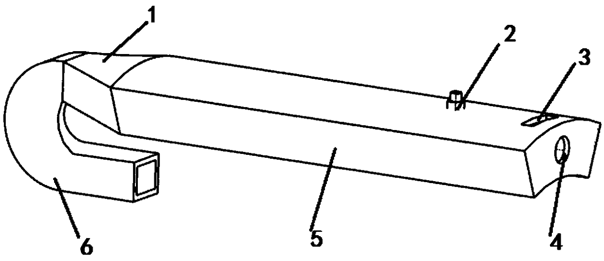
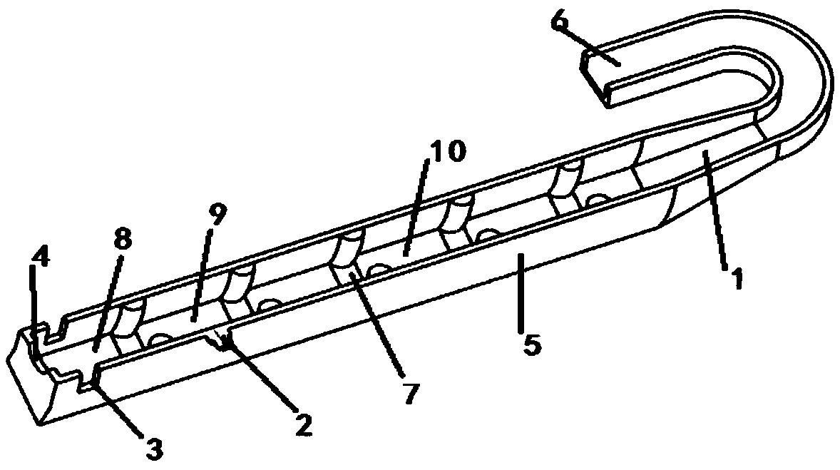
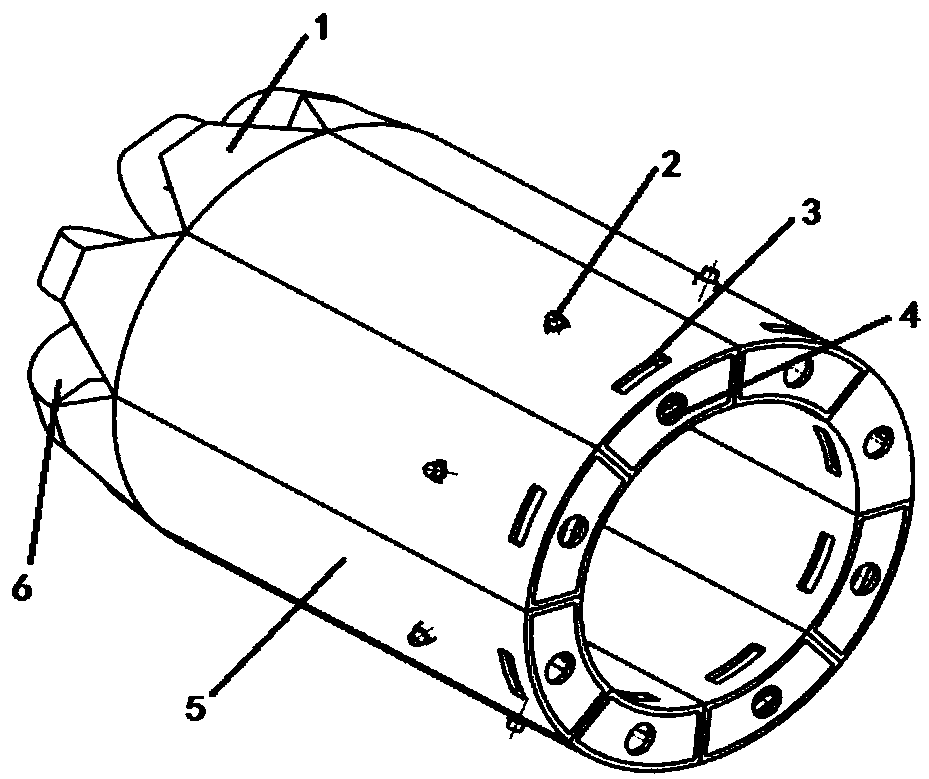
[0018] to combine figure 1 and figure 2 , the present invention proposes a backflow pulse detonation engine detonation tube structure, which can effectively shorten the radial distance of the detonation tube, reduce the mass of the detonation engine, and enable the engine to obtain greater power. figure 1 It is a schematic diagram of the structure of the backflow detonation tube. The backflow detonation tube includes the detonation tube (1, 5, 6), the spark plug (2), the auxiliary air inlet (3), the main air inlet (4), and fan-shaped obstacles (7). The detonation tube is a curved tube structure, which is divided into a fan-shaped straight section (5), a transition section (1) and a rectangular curved section (6). The main air inlet (4) and the auxiliary air inlet (3), the main air inlet (4) is located at the axial inlet, and the fuel injection pipe will extend from the ma...


PUM


Abstract

The invention provides a backflow type detonation tube structure for a pulse detonation engine. With a bent pipeline structure adopted, the axial distance of the detonation tube can be greatly reduced, the axial length of the pulse detonation engine can be decreased, the weight of the pulse detonation engine can be reduced, the structure of a detonation combustion chamber is more compact, the heatcapacity intensity of the combustion chamber can be increased, and the engine can obtain greater thrust / power; and with a fan-shaped pipeline structure adopted, the detonation tube in the combustionchamber is distributed more reasonably, and the capacity of the detonation tube is larger, and therefore, the thrust of the pulse detonation engine can be improved; a fan-shaped obstacle in the detonation tube has a semi-circular cross section, and the fan-shaped obstacle enables a better DDT (deflagration to detonation transition) shortening effect compared with an ordinary rectangular-section obstacle.

Description

technical field [0001] The invention relates to the field of pulse detonation engines, in particular to a backflow type pulse detonation engine detonation tube structure. Background technique [0002] The pulse detonation engine is a new concept propulsion device that uses high-temperature and high-pressure gas generated by pulse detonation waves to generate thrust. It has the advantages of simple structure, small size, high thermal cycle efficiency, wide working range, low pollution, and the highest thrust-to-weight ratio. Up to 20. The pulse detonation engine can be used as the power plant of unmanned aircraft, the power plant of target aircraft or hypersonic stealth reconnaissance aircraft, the power plant of long-range missiles and strategic aircraft, and may also be used as the power propulsion device of military and civilian aircraft and high-altitude aircraft in the future. [0003] Pulse detonation engines can be divided into air-breathing and rocket-type according ...

Claims


Application Information

Patent Timeline
IPC IPC(8): F02K9/62F02K9/60F02K9/44F02K9/95
CPCF02K9/44F02K9/60F02K9/62F02K9/95
Inventor 张群曹婷婷杨福正李程镐刘强张鹏王鑫海涵
Owner NORTHWESTERN POLYTECHNICAL UNIV
Learn More