Three-cylinder type vacuum dryer

A dryer and vacuum technology, applied in the field of dryers, can solve the problems of complex production of heat pipe drying chambers, long drying time, and low exhaust efficiency, so as to increase the effective use area of ​​the site, reduce environmental impact, reduce The effect of heat loss

Inactive Publication Date: 2019-01-15
张国利
View PDF0 Cites 4 Cited by
  • Summary
  • Abstract
  • Description
  • Claims
  • Application Information

AI Technical Summary

Problems solved by technology

[0002] At present, the dryers used for drying materials on the market all use high temperature and strong wind drying. The drying process is down-flow, mixed-flow, counter-current and combined hot air for grain drying. The entire drying process is atmospheric pressure, and there are drying equipment Problems such as large volume, low utilization rate of heat energy, large power consumption, failure to utilize waste heat, poor quality after drying, long drying time, etc.
In response to this situation, people have adopted vacuum drying technology to dry materials in vacuum at low temperature in a low-pressure vacuum state, which solves the problems of high hot air temperature and poor quality of materials after drying; All metal exhaust pipes are placed in parallel to dissipate heat, with low heat conduction and heat dissipation efficiency and low exhaust efficiency
The production of the cooling tube drying chamber of the tumble dryer is complicated, and the failure rate of the cooling tube is high during use, and it is not easy to maintain

Method used


Image

  • Three-cylinder type vacuum dryer
  • Three-cylinder type vacuum dryer
  • Three-cylinder type vacuum dryer

Examples


Embodiment

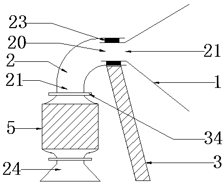
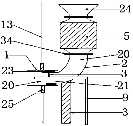
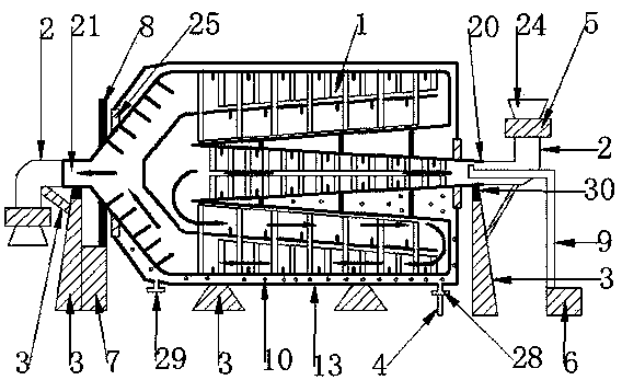
[0197] Such as figure 1 , figure 2 The shown three-cylinder vacuum dryer includes a three-cylinder drying chamber (1), a two-way elbow (2), a bracket (3), a heat pipe (4), a discharge valve (5), and a vacuum unit ( 6), driving device (7), gear ring (8), air duct (9), heat conduction medium (10), heating chamber (13), hopper (1), connecting sealing device (25), supporting wheel (30) .

[0198] There is a set of gear rings (8) on the three-drum drying bin (1).

[0199] 1. The fixed connection between the gear ring (8) and the three-drum drying chamber (1) is integrated.

[0200] The driving device (7) is a motor and a gearbox.

[0201] 1. The driving device (7) is fixedly supported by the bracket (3).

[0202] The supporting roller (30) is installed on the bracket (3).

[0203] 1. The supporting roller (30) supports the discharge port (21) and the feed port (20) of the three-barrel drying bin (1).

[0204] 2. The three-cylinder drying bin (1) is driven by the driving dev...


PUM


Abstract

The invention discloses a three-cylinder type vacuum dryer. The three-cylinder type vacuum dryer comprises a three-cylinder drying cabin, a two-way bend pipe, a bracket, a heat conducting pipe, a discharging valve, a vacuum set, a driving device, a gear ring, an air guide pipe, a heat conducting medium, a heating cabin, a hopper, a connecting sealing device and a riding wheel. Under driving of thedriving device and supporting of the riding wheel, the three-cylinder drying cabin can rotate and work. The discharging valve is used for continuous wet materials in the hopper to enter the three-cylinder drying cabin through the discharging valve. The vacuum set extracts gas in the three-cylinder drying cabin and moisture generated by the drying of the material. The heat conducting medium carrying heat energy in the heating cabin is used for conducting heat conduction and heat dissipation to the material. The heat conversion efficiency is high and the loss is little. When one of heat pipes is damaged, the leakage does not affect the use of the whole three-cylinder type vacuum dryer. The failure rate of the three-cylinder type vacuum dryer is reduced.

Description

technical field [0001] The invention relates to a dryer, in particular to a three-cylinder vacuum dryer. Background technique [0002] At present, the dryers used for drying materials on the market all use high temperature and strong wind drying. The drying process is down-flow, mixed-flow, counter-current and combined hot air for grain drying. The entire drying process is atmospheric pressure, and there are drying equipment Large volume, low heat energy utilization rate, high power consumption, unused waste heat, poor quality after drying, long drying time and other problems. In response to this situation, people have adopted vacuum drying technology to dry materials in vacuum at low temperature in a low-pressure vacuum state, which solves the problems of high hot air temperature and poor quality of materials after drying; All metal exhaust pipes placed in parallel dissipate heat, and the heat conduction and heat dissipation efficiency is low, and the exhaust efficiency is...

Claims


Application Information

Patent Timeline
Patent Type & Authority Applications(China)
IPC IPC(8): F26B11/04F26B11/06F26B7/00F26B23/10F26B25/02F26B25/04F26B25/16F28D15/02
CPCF26B11/0427F26B7/00F26B11/0481F26B23/10F26B25/02F26B25/04F26B25/16F28D15/0275
Inventor 张国利
Owner 张国利
Why Eureka
Try Eureka