
Precision control method for spinning machine

A precision control, spinning machine technology, applied in computer control, program control, general control system and other directions, can solve the problems of manufacturing, installation accuracy error, unknown equipment stability, etc., to achieve the effect of basic force balance

Active Publication Date: 2019-01-15
AVIC BEIJING AERONAUTICAL MFG TECH RES INST
View PDF12 Cites 8 Cited by
  • Summary
  • Abstract
  • Description
  • Claims
  • Application Information

AI Technical Summary

Problems solved by technology

However, the position accuracy of each roller shaft is guaranteed only by the system’s compensation for the position accuracy of each roller shaft, but it ignores that the roller shaft is installed on the column, and the column itself will have manufacturing and installation accuracy errors, and the mandrel will cause eccentricity during the rotation process. The gap between the rotary wheel and the mandrel caused by the combined action of many factors such as errors will have a variety of actual effects as the rotary wheel shaft moves up and down on the column, which will affect the stability of the equipment in the actual spinning process. with unknowable consequences

Method used


Image

  • Precision control method for spinning machine

Examples


Embodiment Construction

[0014] In order to make the present invention easier to understand, the technical solutions of the present invention will be described in detail below in conjunction with the accompanying drawings and embodiments.

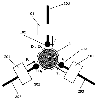
[0015] figure 1 It is a schematic structural principle diagram of an embodiment of a spinning machine precision control method of the present invention. This figure is a structural schematic diagram viewed from above the spinning machine. The center of the spinning machine is a vertical spindle mandrel 4. The mandrel 4 has three vertical columns evenly distributed, namely the first column 101, the second column 201, and the third column. The column 301, the first column 101, the second column 201 and the third column 301 are respectively equipped with a first ram 103, a second ram 203, and a third ram 303 that move laterally, and the first ram 103, The second ram 203 and the third ram 303 are respectively provided with a first rotary wheel 102, a second rotary whe...


PUM


Abstract

The invention discloses a precision control method for a spinning machine, which is controlled by two modes. One is that clearance deviation values of different positions are obtained by calculating through mathematical analysis; compensation is carried out through a horizontal ram position of a rotating wheel, and a clearance error is eliminated. The other one is that the clearance between the rotating wheel and a main shaft is dynamically adjusted by regularly monitoring the pressure of a horizontal ram hydraulic cylinder of the rotating wheel, and each rotating wheel is ensured to be stressed basically in balance, thereby meeting the stable processing requirement of a machine tool and reducing the negative impact of the equipment on the long part spinning process of the large spinning machine tool due to a component machining error, assembly and installation errors, and the like; at the same time, the control system can realize adaptive control, reduce equipment unbalance loading ofthe spinning process, avoid equipment vibration from generating, ensure the stability of the spinning process and ensure the spinning precision.

Description

technical field [0001] The invention relates to an industrial control method, in particular to a precision control method of a spinning machine. Background technique [0002] Large-scale CNC powerful three-wheel spinning machine tool has three vertical columns evenly distributed, the center of which is a vertical spindle mandrel, the parts are set on the mandrel, each column is equipped with a laterally moving ram, and the rotary wheel is fixed in the horizontal direction. Move the front end of the ram, and each rotary wheel moves to the position of contacting the part through the ram, which can realize the synchronous spinning or staggered spinning of the three rotary wheels, and the positive rotation of the part can be realized by moving the three rotary wheels up and down or anti-spin. [0003] In the three-wheel spinning process, the numerical control system determines the amount of spinning by controlling the gap between each wheel and the mandrel. Each spinning part, ...

Claims


Application Information

Patent Timeline
IPC IPC(8): G05B19/404B21D22/14
CPCB21D22/14G05B19/404
Inventor 施万红关大力李维涛李中凯
Owner AVIC BEIJING AERONAUTICAL MFG TECH RES INST
Learn More