Ultra-wideband tightly coupled array antenna

A tightly coupled array and ultra-wideband technology, which is applied to antennas, resonant antennas, antenna arrays, etc., can solve the problems of not very wide antenna bandwidth and complex structure, and achieve the effects of expanding bandwidth, overcoming insufficient bandwidth, and overcoming complex structures

Active Publication Date: 2019-01-15
XIDIAN UNIV
View PDF6 Cites 19 Cited by
  • Summary
  • Abstract
  • Description
  • Claims
  • Application Information

AI Technical Summary

Problems solved by technology

But the bandwidth of the array antenna is not very wide, and the structure is relatively complicated

Method used


Image

  • Ultra-wideband tightly coupled array antenna
  • Ultra-wideband tightly coupled array antenna
  • Ultra-wideband tightly coupled array antenna

Examples


Embodiment Construction

[0028] The present invention will be further described below in conjunction with accompanying drawing:

[0029] Refer to attached figure 1 , figure 2 , image 3 , Figure 4 and Figure 5

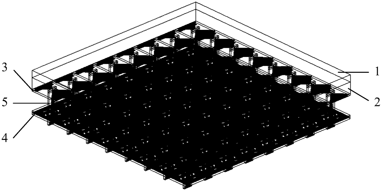
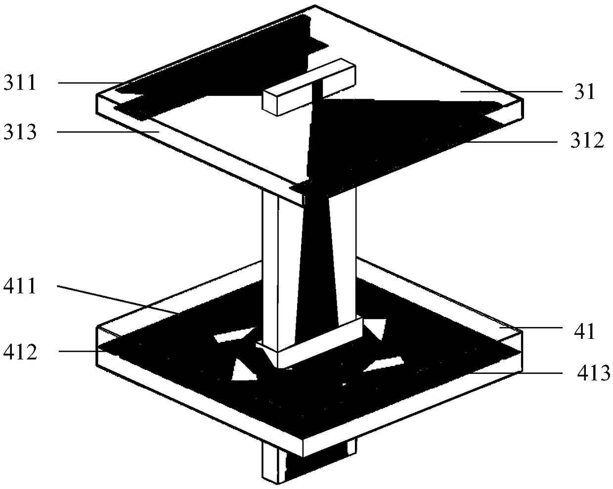
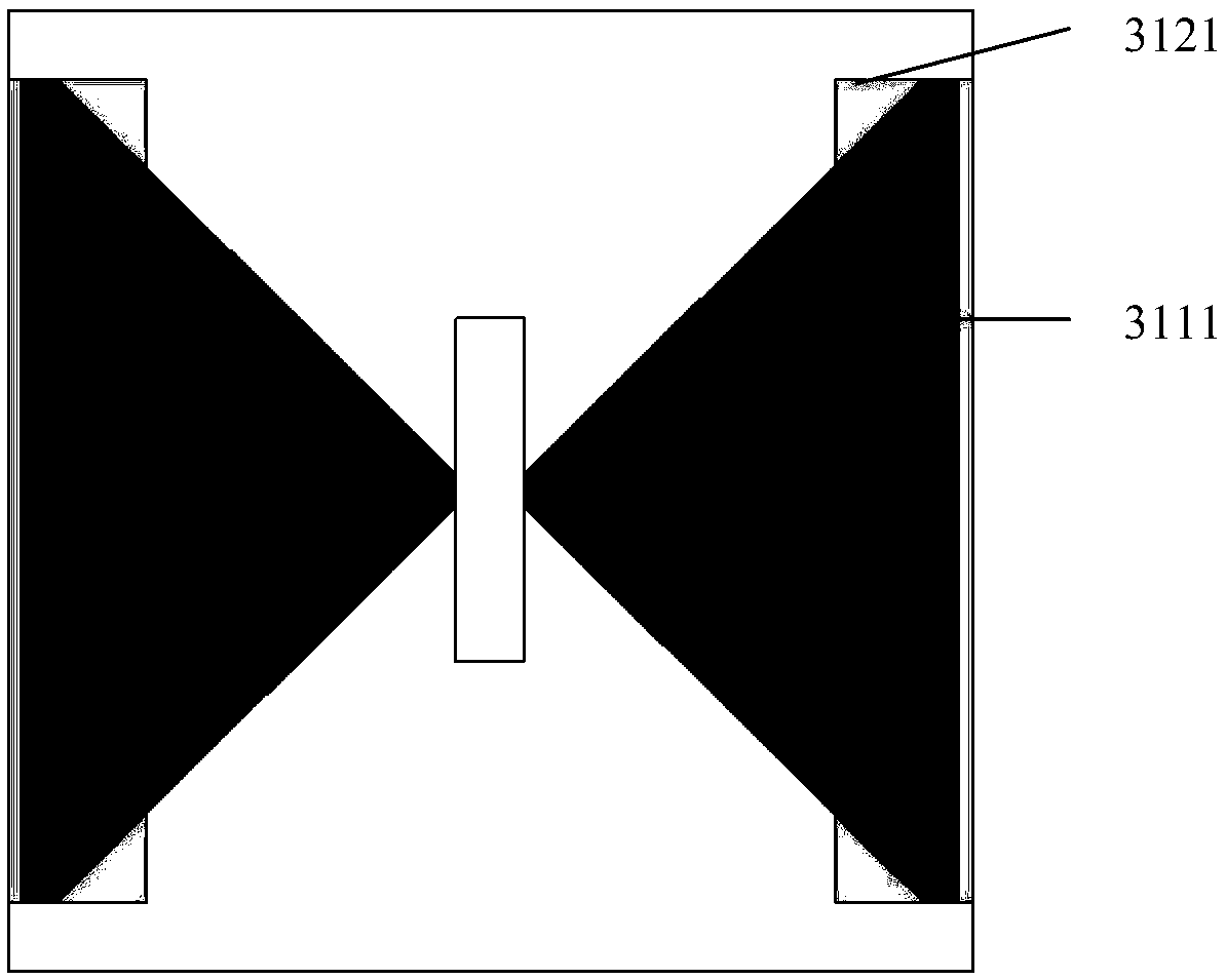
[0030] An ultra-wideband tightly coupled array antenna, comprising a first matching layer 1, a second matching layer 2, an antenna array board 3, a frequency selective surface board 4 and a feeding balun array 5, the first matching layer 1, the second Both the matching layer 2 and the antenna array board 3 are located directly above the frequency selective surface board 4; the antenna array board 3 includes a plurality of dipole radiation period units 31, and each dipole radiation period unit 31 includes a dipole arm 311, coupling metal patch 312 and antenna dielectric plate 313; the frequency selection surface plate 4 includes a plurality of frequency selection surface units 41, the dipole arm 311 is composed of two first metal patches 3111, the coupling The metal patch 312 includes ...


PUM


Abstract

The invention provides a novel ultra-wideband tight coupling array, comprising a first matching layer, a second matching layer, an antenna array board, a frequency selection surface board and a feeding balun array. The antenna array board is positioned directly above the frequency selection surface board. The antenna array plate comprises a plurality of dipole radiation periodic units, each dipoleradiation periodic unit comprises a dipole arm, a coupling metal patch and an antenna dielectric plate; The frequency selective surface plate includes a plurality of frequency selective surface units, the dipole arm is composed of two first metal patches, the coupling metal patch includes two second metal patches, and each frequency selective surface unit is composed of two four-fold circular ring patches, a hexagonal star gap patch and two layers of frequency selective surface dielectric plates. A frequency selective surface is used to eliminate short-circuit points, the VSWR is less than 3in the frequency range of 1.14 GHz to 11.2 GHz, and the array bandwidth can be increased to 9.8 octaves, which can be used in communication and satellite tracking radar systems.

Description

technical field [0001] The invention belongs to the technical field of antennas, and in particular relates to an ultra-wideband tightly coupled array antenna, which can be used in communication and satellite tracking radar systems. Background technique [0002] With the increasing development of modern wireless communication systems, the transmission of a large amount of information such as images, audio, and videos has increased the amount of communication information, and modern society has entered the information age in an all-round way. This puts forward further requirements on the performance of the antenna in various aspects such as bandwidth, gain, and directivity, so that a single independent antenna cannot meet the requirements of high gain and the like. Antenna arrays are widely used because of their advantages such as high gain, phase scanning, and pattern shaping. [0003] In recent years, in order to meet the bandwidth requirements of array antennas, UWB antenn...

Claims


Application Information

Patent Timeline
Patent Type & Authority Applications(China)
IPC IPC(8): H01Q21/06H01Q21/00H01Q9/04H01Q1/38H01Q1/50H01Q15/00
CPCH01Q1/38H01Q1/50H01Q9/045H01Q15/0026H01Q15/0093H01Q21/0006H01Q21/062H01Q21/065
Inventor 张帅王琳龚书喜王露莹黄楠刘雨果张友坤白禅
Owner XIDIAN UNIV
Why Eureka
Try Eureka