Supercharge Your Innovation With Domain-Expert AI Agents!

Charging silt separation device of plug flow reactor

A sediment separation and reactor technology, applied in biological sludge treatment, settling tanks, etc., can solve the problems of low gas production efficiency, poor separation effect, and reduced effective volume of plug flow reactors, so as to reduce heat loss, The effect of increasing the gas production rate and prolonging the cleaning time

Active Publication Date: 2019-01-18
南京和润隆环保科技有限公司
View PDF2 Cites 1 Cited by
  • Summary
  • Abstract
  • Description
  • Claims
  • Application Information

AI Technical Summary

Problems solved by technology

[0002] At present, due to the rapid development of biomass renewable energy, the development and application of aquaculture manure and crop straw, etc., the field of biogas production by anaerobic fermentation of straw manure needs to be more popularized. In the application process, after the manure is collected, it needs It is pumped to the plug-flow reactor for fermentation to produce biogas. During the application process, we found that the inside of the plug-flow reactor needs to be cleaned regularly. The reason is that the feces contain a large amount of sediment and accumulate at the bottom of the plug-flow reactor. In the long run, the effective volume of the plug flow reactor will be greatly reduced, and the gas production efficiency will be low. At this time, how to remove the sediment contained in the front-end manure is an engineering problem that needs to be solved at present
The existing ones also use grit chambers for sand settling, but the separation effect is not good

Method used


Image

  • Charging silt separation device of plug flow reactor
  • Charging silt separation device of plug flow reactor
  • Charging silt separation device of plug flow reactor

Examples


Embodiment Construction

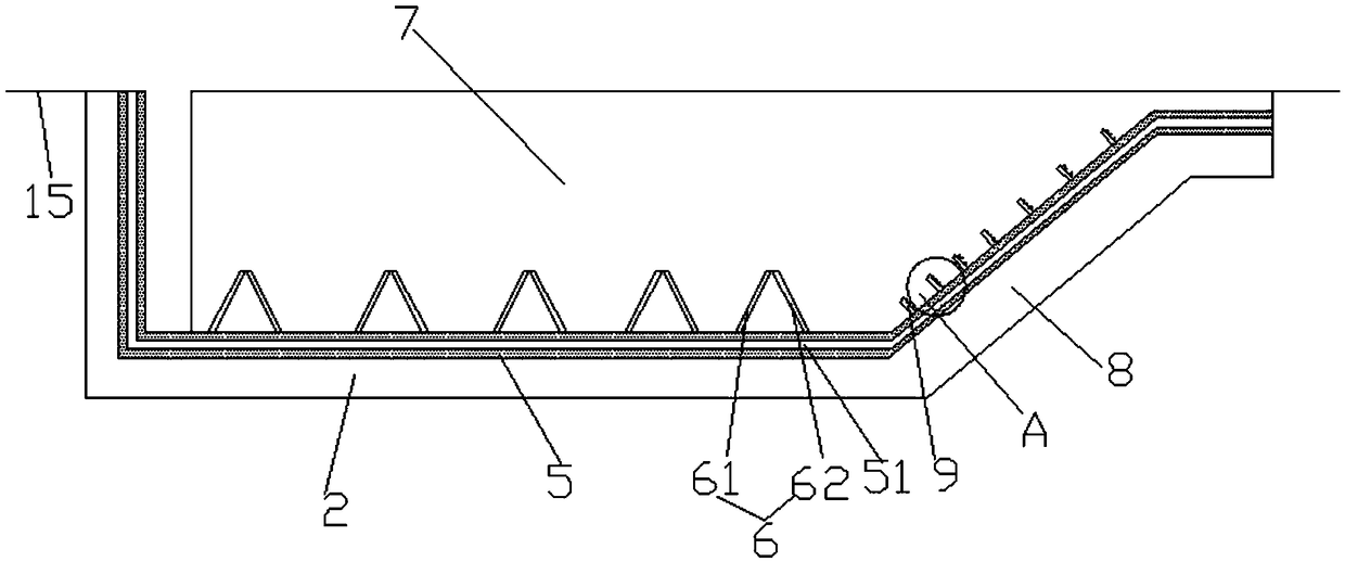
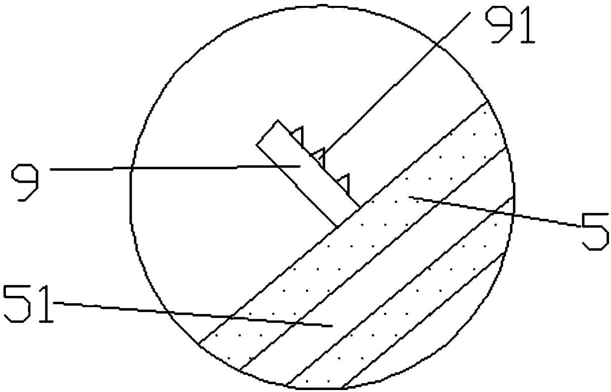
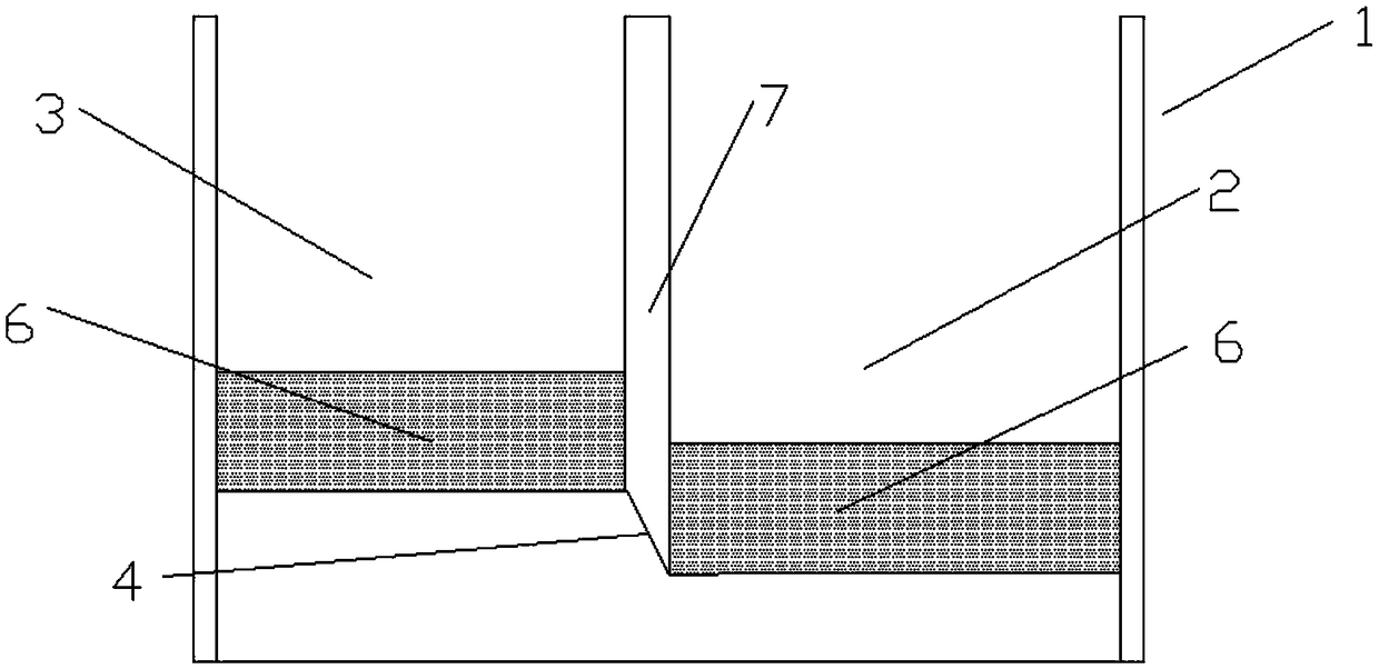
[0023] Such as Figure 1-4 Shown, a kind of plug-flow reactor feeding sediment separation device comprises the settling tank 1 located underground or semi-underground, and the settling tank 1 includes the first settling tank 2 and the second settling tank 3, the first settling tank 2 The feed end of the discharge end and the second settling tank 3 is connected by the transition tank 4, the bottom of the transition tank 4 is inclined, the bottom of the second settling tank 3 is higher than the bottom of the first settling tank 2, and the bottom of the settling tank 1 And the surface of side wall is all provided with thermal insulation layer 5, and thermal insulation layer 5 is provided with vacuum cavity 51, and thermal insulation layer 5 is made of extruded plastic plate, is provided with some baffle plates 6 that can reduce the velocity of sediment flow in the settling tank 1. Wherein, the settlement tank 1 is made of concrete. The invention can realize the sediment separati...


PUM


Abstract

The invention provides a charging silt separation device of a plug flow reactor and in particular relates to the technical field of anaerobic fermentation production of marsh gas. The charging silt separation device comprises a sedimentation tank which is arranged in an underground or semi-underground place, wherein the sedimentation tank comprises a first sedimentation tank and a second sedimentation tank; a discharging end of the first sedimentation tank is connected with a feeding end of the second sedimentation tank through a transition tank and the bottom of the transition tank is obliquely arranged; the bottom of the second sedimentation tank is higher than the bottom of the first sedimentation tank; heat-insulation layers are arranged at the bottom in the sedimentation tank and thesurface of a side wall; each heat-insulation layer is provided with a vacuum cavity; each heat-insulation layer is made of an extrusion plate; the sedimentation tank is internally provided with a plurality of baffle plates which can be used for reducing the flowing speed of silt. According to the charging silt separation device of the plug flow reactor provided by the invention, a lot of the siltis intercepted through primary sedimentation in the first sedimentation tank; the second sedimentation tank is used for further settling to improve the sedimentation effect; furthermore, the sedimentation tank is arranged in the underground or semi-underground place so that heat loss can be reduced; the heat-insulation layers are arranged so that effective heat-insulation measures on excrement areeasy to carry out and subsequent reaction of the plug flow reactor is easy to realize.

Description

technical field [0001] The invention belongs to the technical field of biogas production by anaerobic fermentation, and in particular relates to a feed sediment separation device for a plug flow reactor. Background technique [0002] At present, due to the rapid development of biomass renewable energy, the development and application of aquaculture manure and crop straw, etc., the field of biogas production by anaerobic fermentation of straw manure needs to be more popularized. In the application process, after the manure is collected, it needs It is pumped to the plug-flow reactor for fermentation to produce biogas. During the application process, we found that the inside of the plug-flow reactor needs to be cleaned regularly. The reason is that the feces contain a large amount of sediment and accumulate at the bottom of the plug-flow reactor. If things go on like this, the effective volume of the plug flow reactor will be greatly reduced, and the gas production efficiency ...

Claims


Application Information

Patent Timeline
IPC IPC(8): B01D21/02C02F11/04
CPCB01D21/02C02F11/04
Inventor 阮仕攀宋敏黄加强程勇宋龙杨丰信
Owner 南京和润隆环保科技有限公司
Features
  • R&D
  • Intellectual Property
  • Life Sciences
  • Materials
  • Tech Scout
  • Unparalleled Data Quality
  • Higher Quality Content
  • 60% Fewer Hallucinations
Learn More