Supercharge Your Innovation With Domain-Expert AI Agents!

Two-dimensional vibrating table for precision ultrasonic machining

A technology of ultrasonic machining and two-dimensional vibration, which is applied in the direction of metal processing equipment, metal processing machinery parts, manufacturing tools, etc., can solve the problems of large grinding force, low workpiece surface processing accuracy, low material removal rate, etc., to improve the applicable sexual effect

Pending Publication Date: 2019-01-18
TIANJIN UNIVERSITY OF SCIENCE AND TECHNOLOGY
View PDF0 Cites 5 Cited by
  • Summary
  • Abstract
  • Description
  • Claims
  • Application Information

AI Technical Summary

Problems solved by technology

[0003] The purpose of the present invention is to overcome the problems of low surface machining accuracy, large grinding force, and low material removal rate in the prior art, and provide a two-dimensional ultrasonic vibration table for precision ultrasonic machining that can achieve high efficiency and high precision

Method used


Image

  • Two-dimensional vibrating table for precision ultrasonic machining
  • Two-dimensional vibrating table for precision ultrasonic machining
  • Two-dimensional vibrating table for precision ultrasonic machining

Examples


Embodiment 1

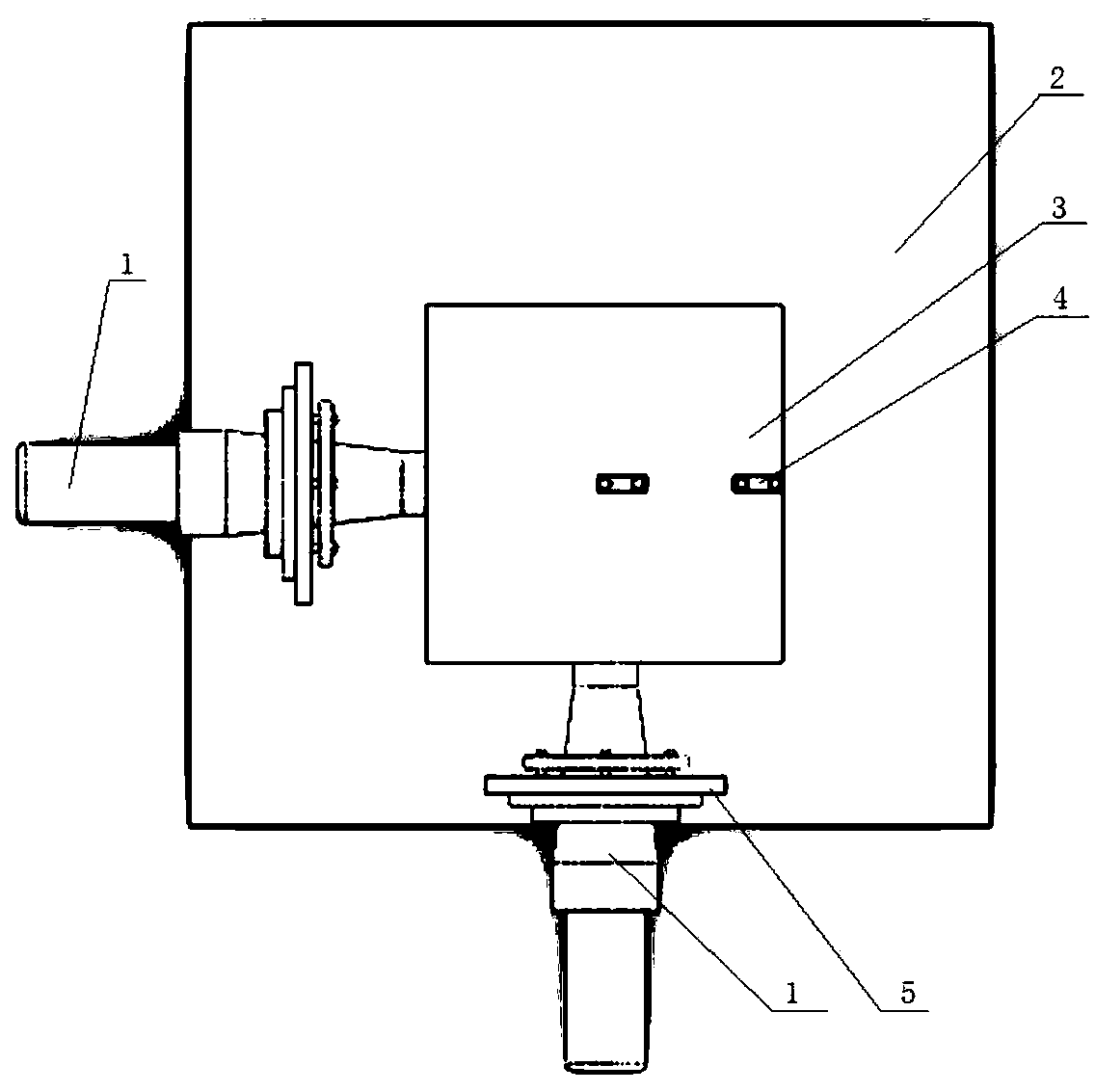
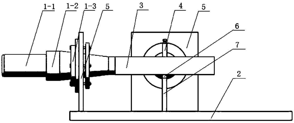
[0029] like figure 1 As shown, the vibrating table supporting frame is installed at the center of the bottom surface of the vibrating table. The vibrating table supporting frame is composed of a column 7 and a supporting ball 6. The supporting ball is fixed on the top surface of the column, and the bottom surface of the column is fixed on the base. The support ball is only in contact with the bottom surface of the vibrating table but is not firmly connected. The column does not press the vibrating table to move upwards, but only provides support in the Z direction.

[0030] The characteristic of this structure is that the supporting frame of the vibrating table and the vibrating table are point supports. Since the contact surface between the supporting frame of the vibrating table and the vibrating table is very close to a point, the energy transmitted by the ultrasonic wave to the supporting frame of the vibrating table will be greatly reduced, and the energy It will be conc...

Embodiment 2

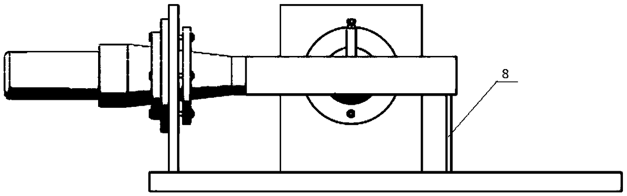
[0032] like image 3 As shown, the vibrating table supporting frame is fixed on one side of the bottom surface of the vibrating table. The vibrating table supporting frame is a support plate 8, the bottom surface of the supporting plate is fixed to the base, and the top surface of the supporting plate only contacts the bottom surface of the vibrating table. But not fixed connection.

[0033] The characteristic of this structure is that: the single support plate of the vibrating table support frame is in contact with the bottom surface of the vibrating table, and the vibrating table supports ultrasonic vibration while the vibrating table support frame does not vibrate. The Z-direction load of the vibration table is supported by a single support plate of the vibration table support frame. This structure is beneficial to reduce the impact of the vibrating table support frame on the overall mode shape of the vibrating table.

[0034] The support plate supporting the vibrating ta...


PUM


Abstract

The invention relates to a two-dimensional vibrating table for precision ultrasonic machining. The two-dimensional vibrating table comprises two ultrasonic vibration devices, a vibration table and a clamp, wherein the two adjacent sides of the vibration table are both provided with the ultrasonic vibration devices, the two ultrasonic vibration devices are perpendicular to each other and are supported through vibration device supporting frames, the bottoms of the two vibration device supporting frames are fixedly mounted on a base, clamps are fixedly mounted on the crisscross wave node faces ofultrasonic waves emitted by the two ultrasonic vibration devices on the top face of the vibration table, a groups of clamps are adopted, and the sizes of the clamps are not too big. The vibration table achieves elliptic motion under the stimulation of the two ultrasonic vibration devices. The two-dimensional vibrating table is designed by utilizing a transducer adopting quarter-wave length, performs supporting by adopting two different supporting modes of thin-plate supporting and point supporting. The vibrating table simultaneously carries out ultrasonic vibration in two directions and performs the motion of an elliptic trajectory on the vibration table top.

Description

technical field [0001] The invention belongs to the field of ultrasonic processing, and relates to a vibrating table, in particular to a two-dimensional vibrating table for precision ultrasonic processing. Background technique [0002] With the development of high technology and material science, special materials such as advanced ceramic materials and alloy materials have been widely used in aerospace, biotechnology, defense industry and other fields. In the process of processing and preparing new materials, special processing is particularly important, such as EDM, ultrasonic processing, electrochemical processing and many other special processing for hard, soft, brittle, heat-sensitive, corrosion-resistant, high melting point, high strength and other special processing. The ideal processing effect can be obtained by processing materials. In this regard, the effect of traditional processing is far inferior to that of special processing, and even cannot be processed. Theref...

Claims


Application Information

Patent Timeline
IPC IPC(8): B23Q1/01B23Q1/74
CPCB23Q1/01B23Q1/74
Inventor 王岩董颖怀赵静楠刘志强张晓峰林彬
Owner TIANJIN UNIVERSITY OF SCIENCE AND TECHNOLOGY
Features
  • R&D
  • Intellectual Property
  • Life Sciences
  • Materials
  • Tech Scout
  • Unparalleled Data Quality
  • Higher Quality Content
  • 60% Fewer Hallucinations
Learn More