
Advanced drilling tool

A technology of advanced drilling and drill bits, applied in drill bits, drilling equipment, earthwork drilling, etc., can solve the problem of low core coring integrity rate, and achieve the effect of ensuring the integrity rate, ensuring the recovery rate, and reducing scour

Pending Publication Date: 2019-01-18
无锡锡钻地质装备有限公司
View PDF9 Cites 2 Cited by
  • Summary
  • Abstract
  • Description
  • Claims
  • Application Information

AI Technical Summary

Problems solved by technology

[0004] However, the current state of the art and existing defects: the core drilling tools used now have a very low core-taking integrity rate when encountering a quicksand layer or a pulverized coal layer. This is a long-standing problem that cannot be solved for many years. Coring rates are often only 10% to 25%

Method used


Image

  • Advanced drilling tool
  • Advanced drilling tool
  • Advanced drilling tool

Examples


Embodiment 1

[0039] A kind of advance drilling tool, comprises inner pipe 37 assembly and outer pipe 36 assembly, and described outer pipe 36 assembly comprises bullet stop head 1, bullet chamber 11, seat ring 17, reamer, outer pipe 36 and Drill bit 43; the inner tube 37 assembly includes fishing spear head 2, recovery pipe 8, bullet caliper 12, suspension cup 16, in-position reporting mechanism, blocked signaling mechanism and inner tube 37, and the lower end of the inner tube 37 exceeds the lower end of the drill bit 43 The lower part of the inner tube 37 is provided with a lower stop spring 41 and an upper stop spring 39 .

[0040] The lower end of the inner tube 37 is 20 to 25 mm beyond the lower end of the drill bit 43 .

[0041] The reamers include an upper reamer 19 and a lower reamer 40 .

[0042]The upper end of the recovery pipe 8 is connected to the spear head 2, the lower end of the recovery pipe 8 is connected to the bullet caliper 12, and the bullet caliper 12 cooperates wit...

Embodiment 2

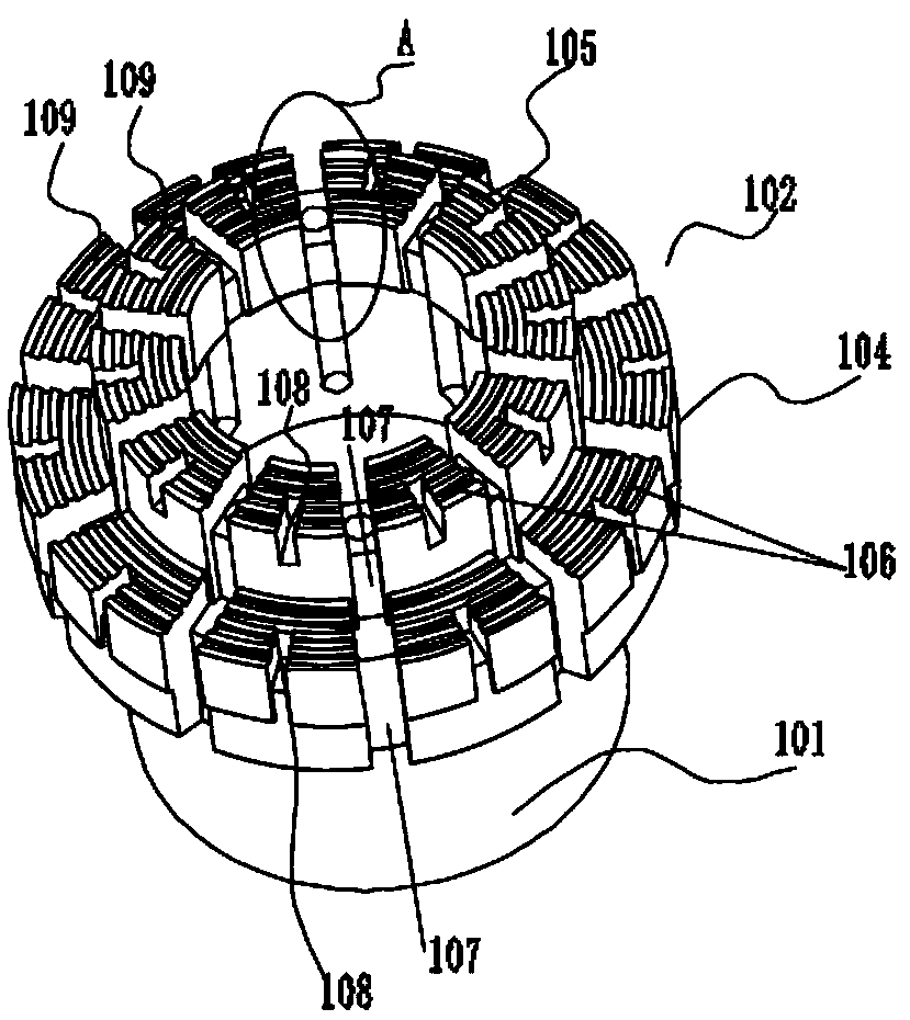
[0054] like Figure 3-Figure 8 As shown, to further optimize the embodiment, the drill bit 43 is a step-shaped drill bit 43, specifically a two-stage drill bit 43, including an outer tube connecting sleeve 101 and an annular drill bit 43 arranged in sequence from the inside to the outside. , the outer pipe connection sleeve 101 and the drill bit 43 are connected through a transition bonding pipe 103; the drill bit 43 includes a second-stage drill bit 104 and a first-stage drill bit 105 from the inside to the outside, and the outer diameter of the first-stage drill bit 105 Smaller than the outer diameter of the second-stage drill bit 104; the second-stage drill bit 104 and the first-stage drill bit 105 are connected to form a coaxial stepped drill bit 43, and the second-stage drill bit 104 and the first-stage drill bit 104 The drill bit 105 is composed of a plurality of cutting teeth 106 of equal height, and the plurality of cutting teeth 106 are evenly distributed around the a...


PUM


Abstract

The invention discloses an advanced drilling tool, comprising an inner tube assembly and an outer tube assembly. The outer tube assembly comprises an elastic clip stop head, an elastic clip chamber, aseat ring, a reamer, an outer tube and a drill bit. The inner tube assembly includes a fishing spearhead, a recovery tube, elastic calipers, a suspension cup, an in-place reporting mechanism, a clogging reporting mechanism, and an inner tube. The advanced drilling tool is characterized in that the lower end portion of the inner tube exceeds the lower end portion of the drill bit, and the lower part of the inner tube is provided with a lower retaining spring and an upper retaining spring. By using the advanced drilling tool, probability of falling blocks is increased, thereby ensuring core recovery percentage, and the core integrity rate is also increased from original 10% to 25% to 85% to 95%.

Description

technical field [0001] The invention relates to an advanced drilling tool. Background technique [0002] In the drilling process, the drill bit is the main tool for breaking rock, and the wellbore is formed by breaking the rock with the drill bit. Whether a wellbore is formed well or not, the length of time it takes is not only related to the characteristics of the drilled formation rock and the performance of the drill bit itself, but also to the degree of matching between the drill bit and the formation. The drill bit is one of the important tools for oil drilling. Whether the drill bit adapts to the rock properties and its quality plays a very important role in the selection of drilling technology, especially in terms of drilling quality, drilling speed and drilling cost. Huge impact, PDC bit is a face-breaking tool widely used in the oil and gas exploration and development industry today, it effectively improves mechanical drilling tools and shortens the drilling cycle....

Claims


Application Information

Patent Timeline
Patent Type & Authority Applications(China)
IPC IPC(8): E21B25/02E21B10/02
CPCE21B10/02E21B25/02
Inventor 徐颂贤张世文
Owner 无锡锡钻地质装备有限公司
Learn More