Eureka AIR delivers breakthrough ideas for toughest innovation challenges, trusted by R&D personnel around the world.

Magnesium-based metal-soluble bridge plug

A magnesium-based metal and bridge plug technology, which is used in wellbore/well components, earthwork drilling, sealing/packaging, etc. problem, to achieve the effect of reliable dissolution performance, rapid dissolution, and increased flow area

Inactive Publication Date: 2019-01-18
CNPC BOHAI DRILLING ENG
View PDF6 Cites 16 Cited by
  • Summary
  • Abstract
  • Description
  • Claims
  • Application Information

AI Technical Summary

Problems solved by technology

Among them, the soluble bridge plug can be completely dissolved in the flowback fluid after fracturing, saving drilling and grinding costs, realizing rapid production, and the wellbore can achieve full diameter, reducing operation risks; however, many limitations have also been found in a large number of on-site constructions Restricted the further popularization and application of this technology
After long-term on-site tracking and analysis, at present, domestic soluble bridge plugs mainly have problems such as premature failure and insolubility after pressing, which greatly limit the popularization and application of this technology
Analysis of the root cause of the above problems is that the materials, structures and construction techniques of soluble bridge plugs are poorly compatible with different well conditions; and this technology has a strong selectivity to well conditions, and it is difficult to solve the problem of soluble bridge plug materials, structures, etc. The matching of technology and different well conditions is the key to the technology

Method used


Image

  • Magnesium-based metal-soluble bridge plug
  • Magnesium-based metal-soluble bridge plug
  • Magnesium-based metal-soluble bridge plug

Examples


Embodiment Construction

[0027] The present invention will be further described below in conjunction with the accompanying drawings and specific embodiments, but the following embodiments in no way limit the present invention.

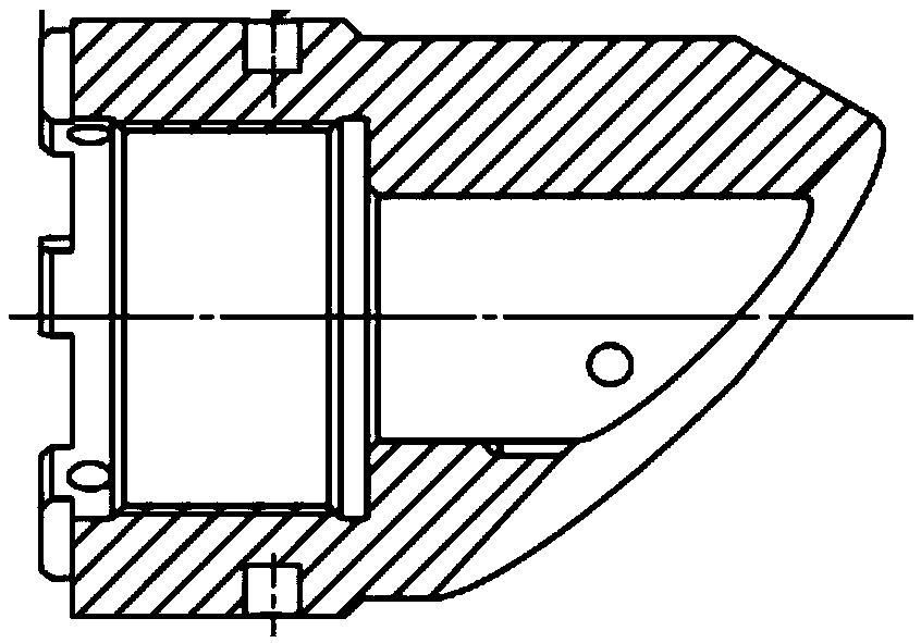
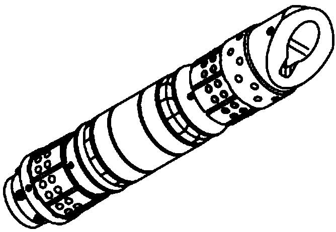
[0028] A magnesium-based metal dissolvable bridge plug, such as Figure 1~4 As shown, it includes central tube 3, throwing shear nails 4, spacer ring 5, upper slips 7, upper vertebral body 10, rubber tube 11, protective ring 12, lower vertebral body 13, lower slips (14) and base (15 ); the spacer ring 5, the upper slip 7, the upper vertebral body 10, the rubber tube 11, the protective ring 12, the lower vertebral body 13, and the lower slips 14 are set on the central tube 3 from top to bottom in sequence, and the base 15 passes through The external thread at the lower end of the central tube 3 is connected to the central tube 3; the upper end of the central tube 3 is fixed on the connecting head of the setting cylinder through the shear nail 4, and the upper end of the connect...


PUM


Abstract

The invention discloses a magnesium-based metal-soluble bridge plug. The magnesium-based metal-soluble bridge plug comprises a central tube, a releasing shear nail, a spacer ring, an upper slip, an upper conical body, a rubber cylinder, a protective ring, a lower conical body, a lower slip, a base and an anti-blocking pattern tube; the spacer ring, the upper slip, the upper conical body, the rubber cylinder, the protective ring, the lower conical body and the lower slip separately sleeve the central tube from top to bottom in sequence, and the base is connected with the central tube through anexternal thread of the lower end of the central tube; the upper end of an outer setting cylinder is connected with an ignition setting tool through a T-shaped thread. Compared with the prior art, themagnesium-based metal-soluble bridge plug has the advantages that a magnesium-based soluble metal material is adopted, and the dissolution performance is reliable; an upper-and-lower bidirectional integral slip structure is adopted, the integral slip junction is broken when the thrust reaches 2-3 t, and the slips are opened; slip teeth adopt combinations of ceramic particles and alloy particles to ensure an anchoring effect and an anchoring force; the base has an anti-rotation structure design, and the plug is drilled conveniently when plug drilling is needed in a short time due to sand blockage or complicated well bottom conditions.

Description

technical field [0001] The invention relates to the technical field of oil and gas field exploitation, in particular to a magnesium-based metal soluble bridge plug. Background technique [0002] With the good results in the development of shale gas and low-permeability oil and gas reservoirs, the staged fracturing technology of horizontal wells has become the main technology for the production stimulation and development of unconventional resources such as shale gas, low-permeability oil and gas, and coalbed methane. As one of the important tools for staged fracturing, bridge plugs are increasingly widely used. Among them, the soluble bridge plug can be completely dissolved in the flowback fluid after fracturing, saving drilling and grinding costs, realizing rapid production, and the wellbore can achieve full diameter, reducing operation risks; however, many limitations have also been found in a large number of on-site constructions This restricts the further popularization...

Claims


Application Information

Patent Timeline
Patent Type & Authority Applications(China)
IPC IPC(8): E21B33/134E21B33/122
CPCE21B33/122E21B33/134
Inventor 詹鸿运冯强刘志斌郭鸣韩永亮张镇丁柯宇赵鹏李梅李娜崔振锚王学正张鹏骆劲羽任正军
Owner CNPC BOHAI DRILLING ENG
Why Eureka
Eureka Blog
Learn More