Liquid crystal optical switch for optical phased array scanning

An optical phased array and optical switch technology, applied in the field of optical phased arrays, can solve the problems of inability to electronically control scanning and depth focusing control, and inability to use beam phase modulation.

Inactive Publication Date: 2019-01-18
NORTH CHINA UNIV OF WATER RESOURCES & ELECTRIC POWER
View PDF11 Cites 1 Cited by
  • Summary
  • Abstract
  • Description
  • Claims
  • Application Information

AI Technical Summary

Problems solved by technology

[0003] When the existing common single-layer liquid crystal optical switch array is applied to the screen display, several column (or row) units in a row (or column) are strobed through the row and column signals, and then the scanning row (or column) is turned off. And scan the adjacent next

Method used


Image

  • Liquid crystal optical switch for optical phased array scanning
  • Liquid crystal optical switch for optical phased array scanning
  • Liquid crystal optical switch for optical phased array scanning

Examples


Embodiment Construction

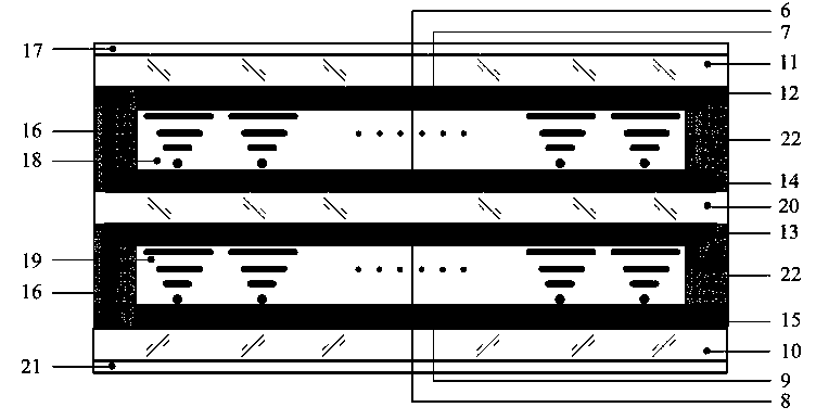
[0031] Such as figure 1 , 2 , 3 and 4, the present invention is composed of a first layer of liquid crystal panel 18 and a second layer of liquid crystal panel 19 arranged up and down, and the first layer of liquid crystal panel 18 is successively provided with row first orientation film 7, Row scanning electrode 12, upper layer glass plate 11 and upper polarizing plate 17, the second alignment film 6, row signal electrode 14 and middle glass plate 20 are arranged in parallel successively below the first layer liquid crystal plate 18; The second layer liquid crystal plate 19 The third alignment film 8 and the column scanning electrode 13 are arranged in parallel on the top, and the fourth alignment film 9, the column signal electrode 15, the lower glass plate 10 and the lower polarizer 21 are arranged in parallel on the bottom of the second layer of liquid crystal panel 19; The row signal electrodes 14 and the column signal electrodes 15 are respectively connected with electr...


PUM


Abstract

The invention discloses a liquid crystal optical switch for optical phased array scanning, and an assembly manufacturing method. The switch is composed of a first layer of liquid crystal panel and a second layer of liquid crystal panel which are arranged in an up-down manner; a first directional thin film, a row scanning electrode, an upper layer glass plate and an upper polarizer are sequentiallyarranged on the upper surface of the first layer of the liquid crystal panel in parallel; a second directional thin film, a row signal electrode and a middle glass plate are sequentially arranged onthe lower surface of the first layer of the liquid crystal panel in parallel; a third directional thin film and a column scanning electrode are sequentially arranged on the upper surface of the secondlayer of the liquid crystal panel in parallel; and a fourth directional thin film, a column signal electrode, a lower layer glass plate and a lower polarizer are sequentially arranged on the lower surface of the second layer of the liquid crystal panel in parallel. Double layers of structures are made into an optical switch plane array with independent controllable units; through the on/off control of a unit switch, the phase modulation is carried out on light beams passing through the unit switch; the plane array is matched with a grating array and a scanning drive circuit to form a laser array scanning device with an optical phased array function; and the orientation and pitching scanning and the depth focusing can be realized.

Description

technical field [0001] The invention relates to the technical field of optical phased arrays, in particular to a liquid crystal optical switch for optical phased array scanning control and an assembly manufacturing method. Background technique [0002] At present, with the rapid development of artificial intelligence technology, target detection, weapon guidance, unmanned driving, autonomous obstacle avoidance and other application fields urgently need a fast, accurate and all-round target detection technology. Radar is the most commonly used detection method. Compared with the radar of traditional mechanical scanning technology, phased array scanning technology uses a large number of independently controlled small antenna units arranged into an antenna array, and each antenna unit is controlled by an independent phase shift switch. By controlling the phases emitted by each antenna element, beams of different phases can be synthesized. Inspired by phase-controlled electroni...

Claims


Application Information

Patent Timeline
IPC IPC(8): G02F1/1343G02F1/13G02F1/1347G02F1/1337G02F1/1335G02F1/133
CPCG02F1/1313G02F1/133G02F1/133528G02F1/133711G02F1/133784G02F1/134309G02F1/1347
Inventor 陈建明王成凤白磊郭香静赵明明王为术陈嘉琦郏一方袁瑞李琛时铭慧张盼盼
Owner NORTH CHINA UNIV OF WATER RESOURCES & ELECTRIC POWER
Why Eureka
Try Eureka