
Monitoring and reconstruction methods of software-defined PLC (Programmable Logic Controller) and devices

A software-defined and reconstructed instruction technology, applied in the field of PLC, to achieve the effect of improving disaster tolerance, easy maintenance, and improving real-time performance

Active Publication Date: 2019-01-18
KYLAND TECH CO LTD
View PDF4 Cites 9 Cited by
  • Summary
  • Abstract
  • Description
  • Claims
  • Application Information

AI Technical Summary

Problems solved by technology

However, if multiple hard PLCs and corresponding redundant PLCs in a certain area fail, since the hard PLCs in another area are working normally, and the PLCs in the two areas affect each other, at this time , can only stop the entire distributed control system to replace the hard PLC in the faulty area

Method used


Image

  • Monitoring and reconstruction methods of software-defined PLC (Programmable Logic Controller) and devices
  • Monitoring and reconstruction methods of software-defined PLC (Programmable Logic Controller) and devices
  • Monitoring and reconstruction methods of software-defined PLC (Programmable Logic Controller) and devices

Examples


Embodiment 1

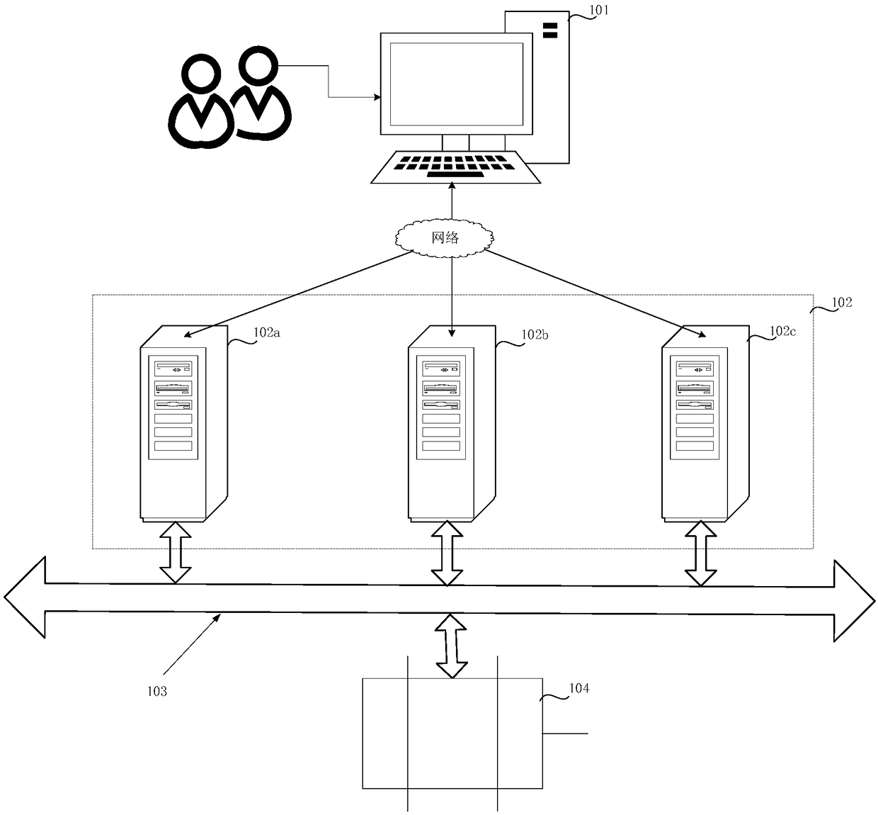
[0054] figure 1 A schematic diagram of the structure of a distributed disaster recovery device applying the embodiment of the present invention is shown. Such as figure 1 As shown, the system architecture may include a client 101 , a server cluster 102 , an input / output (Input / Output, I / O for short) bus 103 , and a device 104 to be controlled. figure 1 Take the server cluster including server 102a, server 102b and server 102c as an example for illustration. The client 101 is connected with each server in the server cluster 102 by wired or wireless mode; the server 102a, the server 102b and the server 102c are connected by wired or wireless mode; the server 102a, the server 102b and the server 102c are respectively connected with The devices to be controlled 104 are connected through the I / O bus 103 .

[0055]Application development environment software, such as integrated development environment (Integrated Development Environment, IDE for short) software, is deployed on th...

Embodiment 2

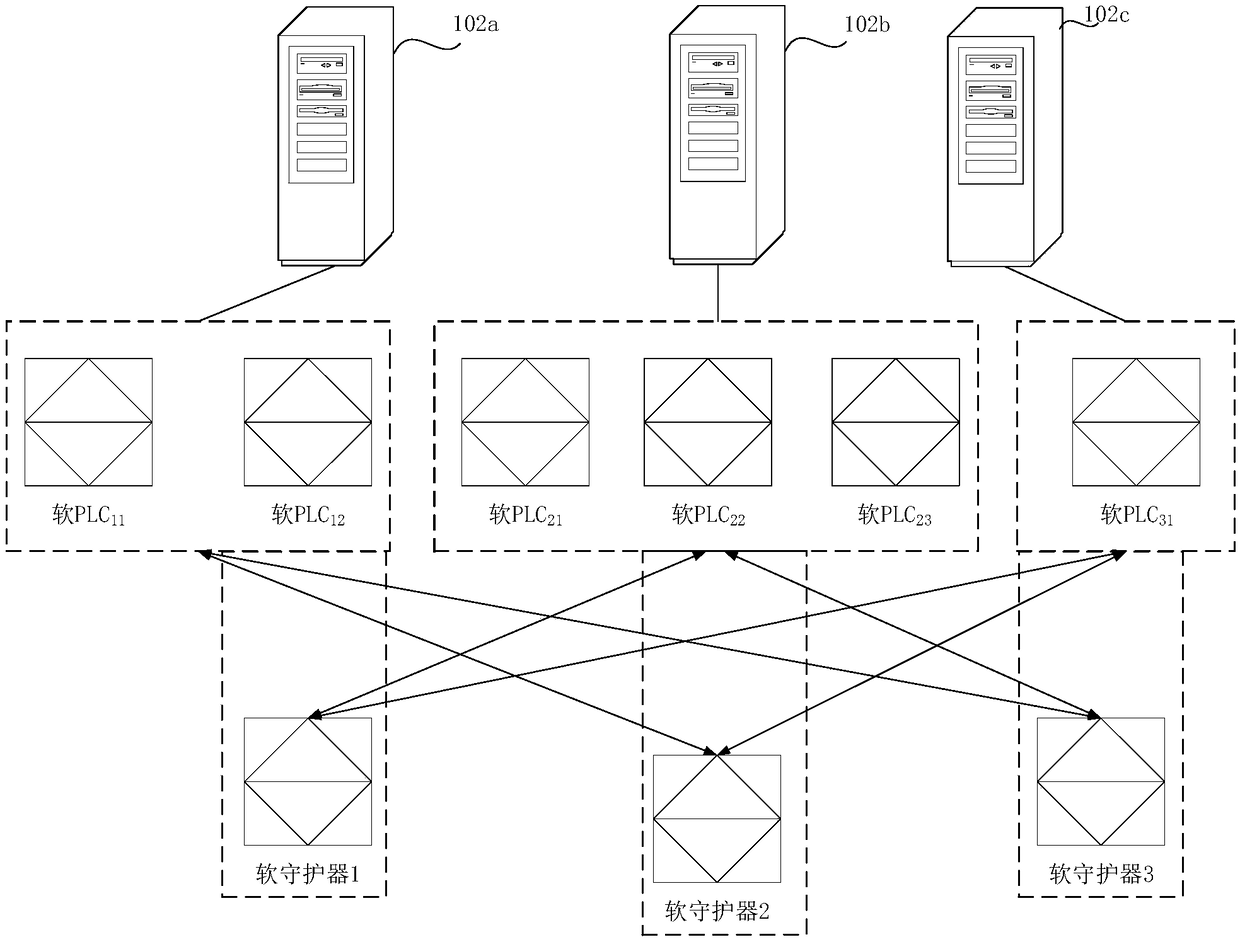
[0091] On the basis of Embodiment 1, each server in the server cluster in this embodiment includes one or more physical cores, and multiple microkernels run on each physical core. The microkernel in this embodiment can be a virtualized real-time operating system, and the physical core can be a CPU physical core. Wherein, the virtualized real-time operating system can be a virtualized operating system with multiple Unix-like kernels installed, for example, a "Tao" Intewell OS system, in which the Unix kernel software is a multi-user, multi-task operating system that supports multiple processor architecture time-sharing operating systems. Based on the control logic of the PLC distributed control system, the PLC distributed control system includes multiple virtual PLCs with relationships, and each virtual PLC runs on a different microkernel. When a virtual PLC fails, the virtual PLC can be reconstructed to realize the corresponding functions of the failed virtual PLC.

[0092] ...


PUM


Abstract

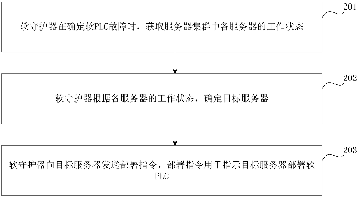
The embodiment of the invention relates to the field of PLC (Programmable Logic Controller), and particularly to monitoring and reconstruction methods of software-defined PLC and devices. The methodsand the devices are used for quickly reconstructing the virtual PLC in a case without powering-down. The method includes: obtaining working status of each physical core on each server in a server cluster and working status of each micro kernel on each physical core by a soft guarder when a fault of the virtual PLC is monitored; determining a target micro-kernel according to the working status of each physical core on each server in a server cluster and the working status of each micro kernel on each physical core; and sending a reconstruction instruction to the target micro-kernel, wherein thereconstruction instruction is used for indication of reconstructing the virtual PLC on the target micro-kernel. Multiple micro kernels are virtualized on one physical core, and thus the virtual PLC runs on a micro kernel; and the PLC is reconstructed on the other micro kernel if the virtual PLC fails, all the micro kernels do not impact one another, and thus fast reconstruction of the virtual PLCcan be realized in the case without powering-down when the virtual PLC is reconstructed.

Description

[0001] This application claims the priority of the Chinese patent application submitted to the China Patent Office on December 22, 2017, the application number is 201711407327.0, and the title of the invention is "a disaster recovery method and device for a PLC-based distributed control system", all of which The contents are incorporated by reference in this application. technical field [0002] The embodiments of the present invention relate to the field of PLCs, in particular to a method and device for monitoring and reconfiguring a software-defined PLC. Background technique [0003] With the continuous development of computer technology, signal processing technology, control technology network and the continuous improvement of user needs, Programmable Logic Controller (PLC) has been widely used. Such as steel, petroleum, chemical industry, electric power, machinery manufacturing, express delivery and cultural entertainment and other industries. Especially in the applicat...

Claims


Application Information

Patent Timeline
Patent Type & Authority Applications(China)
IPC IPC(8): G05B19/05
CPCG05B19/058G05B2219/1204G06F9/45533G06F11/203G06F11/2035G06F11/301G06F2009/45575G05B2219/14006
Inventor 宋健玮
Owner KYLAND TECH CO LTD
Learn More