An on-chip rc oscillator circuit

An oscillator and comparator circuit technology, applied in the field of on-chip RC oscillator circuits, can solve the problems of high power consumption and complex oscillator circuit structure, and achieve the effects of reduced power consumption, simple structure and simple structure

Active Publication Date: 2022-05-06
CHINA KEY SYST & INTEGRATED CIRCUIT
View PDF4 Cites 0 Cited by
  • Summary
  • Abstract
  • Description
  • Claims
  • Application Information

AI Technical Summary

Problems solved by technology

[0004] The purpose of the present invention is to provide an on-chip RC oscillator circuit to solve the problems of complex structure and high power consumption of the existing oscillator circuit

Method used


Image

  • An on-chip rc oscillator circuit
  • An on-chip rc oscillator circuit
  • An on-chip rc oscillator circuit

Examples


Embodiment 1

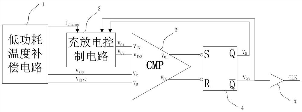
[0021] The present invention provides an on-chip RC oscillator circuit, the structure of which is as follows figure 2 shown. The on-chip RC oscillator circuit includes a low power consumption temperature compensation circuit 1 , a charging and discharging control circuit 2 , a comparator circuit 3 , an RS flip-flop 4 and a buffer 5 .

[0022] Specifically, the first output terminal of the low power consumption temperature compensation circuit 1 outputs a current I charge To the first input terminal of the charging and discharging control circuit 2, the second output terminal outputs the reference voltage V REF and the bias voltage output by the third output terminal V BIAS respectively connected to the reference voltage input terminal V of the comparator circuit 3 R and bias voltage input V B ; The voltage V generated by the first output terminal and the second output terminal of the charge and discharge control circuit 2 C1 , V C2 respectively output voltages to the tw...


PUM


Abstract

The invention discloses an on-chip RC oscillator circuit, which belongs to the technical field of integrated circuits. The on-chip RC oscillator circuit includes a low power consumption temperature compensation circuit, a charge and discharge control circuit, a comparator circuit, an RS flip-flop and a buffer. In the low power consumption stable compensation circuit, the first NMOS transistor, the first PMOS transistor, the fourth PMOS transistor, the third resistor and the second NMOS transistor constitute a circuit that generates a bias current with a negative temperature coefficient; the second NMOS transistor, the second PMOS transistor The tube, the third PMOS tube, the third NMOS tube, and the second resistor form a loop that generates a positive temperature coefficient current; the two loops are connected through the second NMOS tube to achieve negative feedback, and the first capacitor and the first resistor are connected to the negative feedback loop. Le compensation improves stability, only four current branches are required to realize the positive and negative temperature coefficient current structure required for temperature compensation, and the power consumption is reduced; the first NMOS tube, the second NMOS tube, and the third NMOS tube work at sub-threshold The region realizes smaller bias current and lower power consumption.

Description

technical field [0001] The invention relates to the technical field of integrated circuits, in particular to an on-chip RC oscillator circuit. Background technique [0002] Traditional clocks are usually generated using crystal oscillators that work stably and whose oscillation frequency is less affected by power supply, temperature, and process. However, the use of an external crystal oscillator requires two additional circuit ports, and the use of external capacitors and other devices is required, which increases the overall device cost. With the increasing integration of integrated circuits, the use of on-chip RC oscillator circuits compatible with standard CMOS processes to generate clocks is gradually used in digital-analog hybrid circuits. [0003] Such as figure 1 Shown is a traditional structure RC oscillator circuit, the principle of which is to pass the charging current I C and discharge current I D For capacitance C 0 To charge and discharge, the capacitor C ...

Claims


Application Information

Patent Timeline
Patent Type & Authority Patents(China)
IPC IPC(8): H03B5/04H03B5/20
CPCH03B5/04H03B5/20
Inventor 朱晓宇史兴强许卫明庄志伟刘俐
Owner CHINA KEY SYST & INTEGRATED CIRCUIT
Why Eureka
Try Eureka