Optical path system of laser radar, and laser radar

A technology of optical path system and laser radar, which is applied in the direction of radio wave measurement system, electromagnetic wave re-radiation, utilization of re-radiation, etc., can solve the problems of rotating structure wear, high cost, high processing precision requirements, etc., to achieve increased density, increased large area effect

Pending Publication Date: 2019-01-22
HANGZHOU OLE SYST CO LTD
View PDF0 Cites 6 Cited by
  • Summary
  • Abstract
  • Description
  • Claims
  • Application Information

AI Technical Summary

Problems solved by technology

[0004] The machining precision of the mechanical rotating structure of the existing mechanical laser radar is high, and the rotating structure is easy to wear during use, and the long-term stability is poor
In addition, in order to obtain higher resolution, mechanical lidar generally requires multi-line measurement, and uses multiple lasers at the same time, which is costly
[0005] Since the mechanical laser radar realizes surface scanning through the rotation of multiple parallel lasers, its scanning area and density are small, which is difficult to meet the needs of the market.

Method used


Image

  • Optical path system of laser radar, and laser radar
  • Optical path system of laser radar, and laser radar
  • Optical path system of laser radar, and laser radar

Examples


Embodiment Construction

[0030] The advantages of the present invention will be further elaborated below in conjunction with the accompanying drawings and specific embodiments.

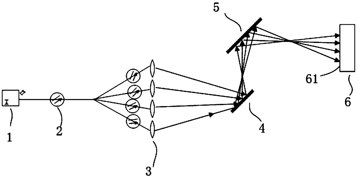
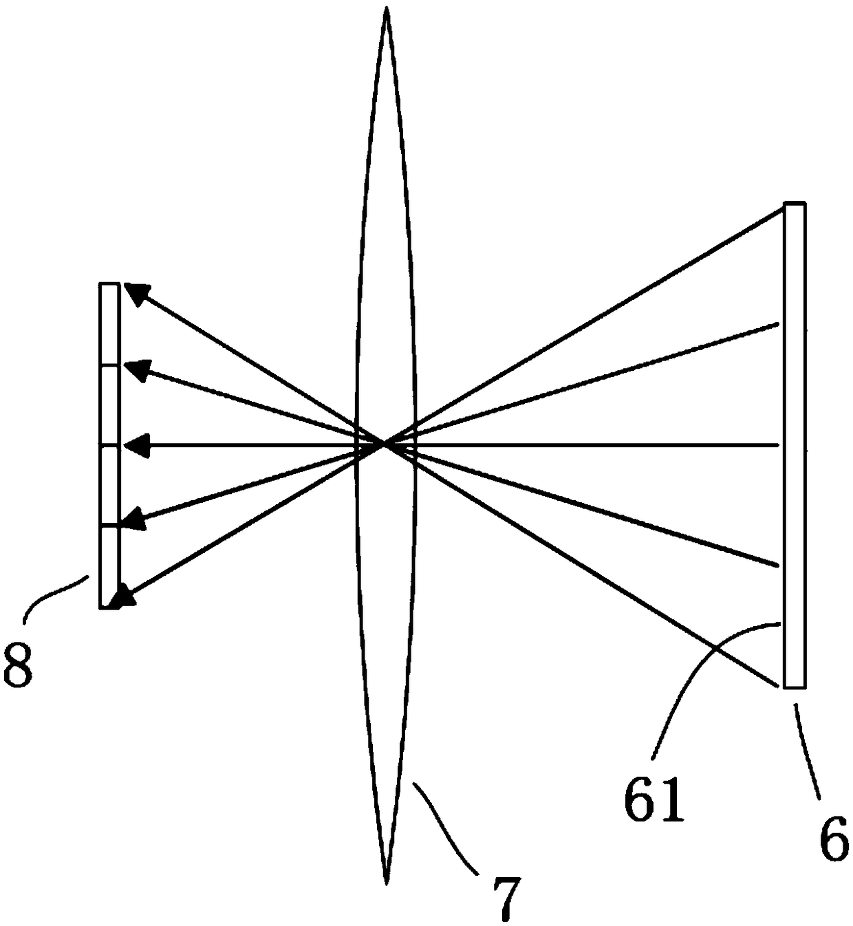
[0031] See attached figure 1 , attached figure 2 , is an optical path system of a laser radar, and the optical path system includes:

[0032] - Laser source 1 for emitting laser light. Preferably, the laser source 1 may be a solid-state laser or a semiconductor laser or a gas laser, and the solid-state laser may preferably be a fiber laser.

[0033] - An optical fiber 2, the optical fiber 2 is connected to the laser source 1, allows the laser to pass through, and divides the laser into no less than two laser beams. Preferably, the optical fiber 2 is provided with a laser beam splitter for splitting the laser light into multiple beams. The laser beam splitter is preferably a one-dimensional linear beam splitter.

[0034] - a collimator lens 3, the collimator lens 3 is arranged in the outgoing direction of the laser beam,...


PUM


Abstract

The invention provides an optical path system of a laser radar, and the laser radar with such optical path system. The optical path system comprises a laser source, an optical fiber, a collimating lens, a first vibrating mirror, a second vibrating mirror, a convergence lens and a receiving device, wherein the laser source emits laser light, the laser light is split into at least two laser beams through the optical fiber, the laser beams are collimated through the collimating lens and then irradiate towards the first vibrating mirror, are further reflected towards the second vibrating mirror bythe first vibrating mirror, and then are reflected towards a target object through the second vibrating mirror. The first vibrating mirror and the second vibrating mirror moves towards different directions at different frequencies. The laser beams reflected back from the target object are converged through the convergence lens and then received by the receiving device. By the technical scheme above, the laser radar has no need of a mechanical rotational structure and a plurality of laser devices, and has bigger scanning area and higher scanning density.

Description

technical field [0001] The invention relates to the technical field of laser radar, in particular to an optical path system of laser radar and a laser radar. Background technique [0002] LiDAR technology is widely used in navigation, map surveying, satellite positioning and other fields. In the field of autonomous driving, lidar plays a key role in map mapping and scene positioning. [0003] Most of the existing lidars are mechanical lidars. Mechanical lidar generally requires a mechanical rotation mechanism, which drives the lidar system to perform spatial rotation scanning through rotation. [0004] The machining precision of the mechanical rotating structure of the existing mechanical laser radar is high, and the rotating structure is easy to wear during use, and the long-term stability is poor. In addition, in order to obtain higher resolution, mechanical lidar generally requires multi-line measurement and uses multiple lasers at the same time, which is expensive. ...

Claims


Application Information

Patent Timeline
IPC IPC(8): G01S17/02G01S7/481
CPCG01S7/4814G01S7/4816G01S7/4817G01S17/02Y02A90/10
Inventor 张瓯朱亚平贺广博
Owner HANGZHOU OLE SYST CO LTD
Why Eureka
Try Eureka