Inverter parallel control method based on improved droop control

A control method and inverter technology, applied in the direction of single-network parallel feeding arrangement, etc., can solve the problems of weak anti-interference ability of the system and low precision of system power distribution, so as to improve anti-interference ability, solve inaccurate power distribution, The effect of improving accuracy

Active Publication Date: 2019-01-22
HARBIN UNIV OF SCI & TECH
View PDF6 Cites 7 Cited by
  • Summary
  • Abstract
  • Description
  • Claims
  • Application Information

AI Technical Summary

Problems solved by technology

When the microgrid is running in an isolated island, the reasonable distribution of the output power of the microgrid inverters according to the capacity is an important control goal for the parallel operation of the inverters. low problem

Method used


Image

  • Inverter parallel control method based on improved droop control
  • Inverter parallel control method based on improved droop control
  • Inverter parallel control method based on improved droop control

Examples


Embodiment Construction

[0035] The present invention will be further described below in combination with specific embodiments.

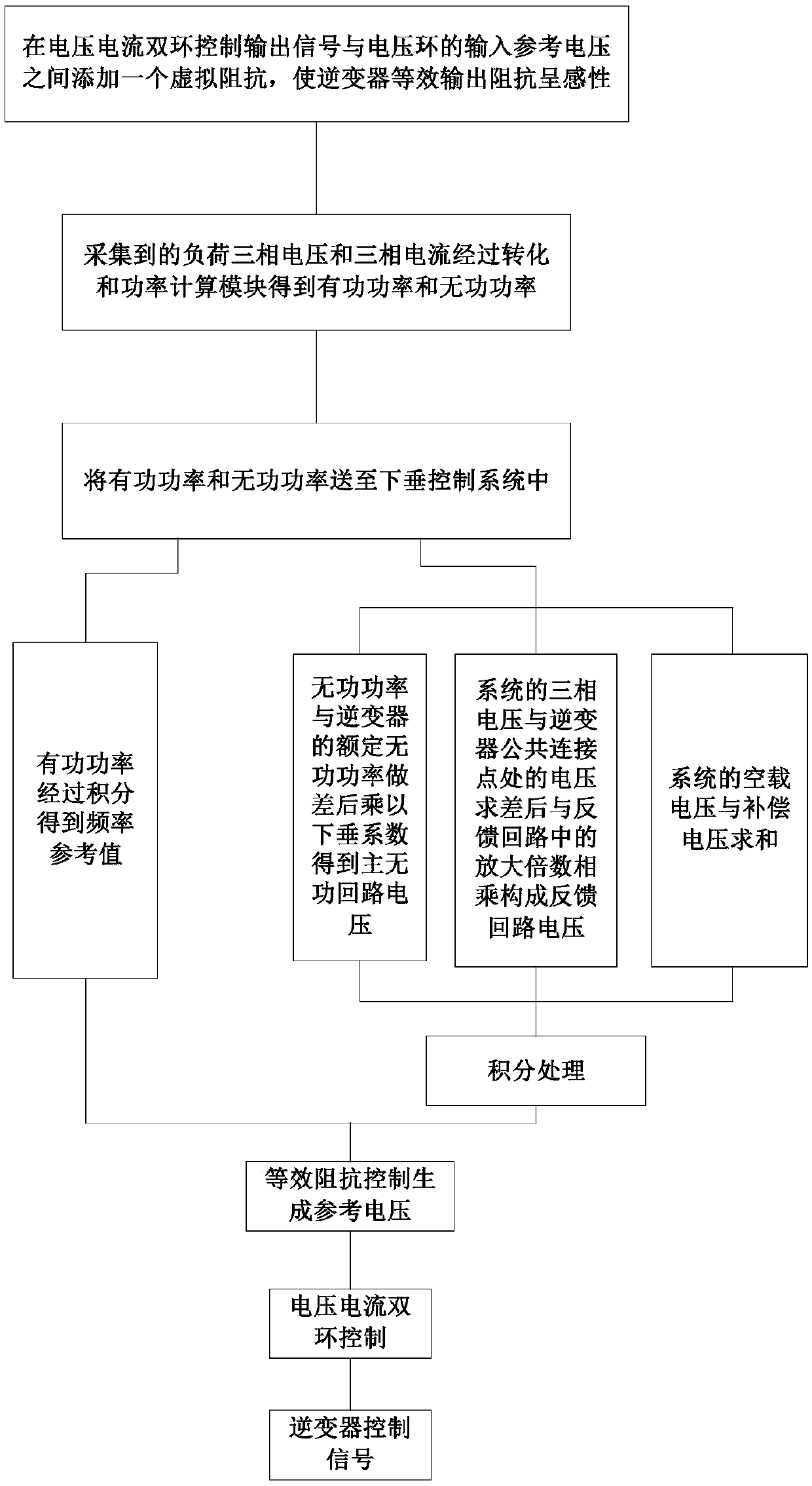
[0036] Such as figure 1 As shown, an inverter parallel control method based on improved droop control in this embodiment includes the following steps:

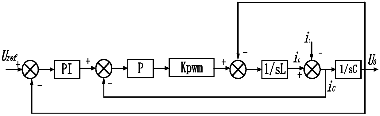
[0037] Step 1. Control the output signal Uo of the voltage and current double loop and the input reference voltage U of the voltage loop ref Add a virtual impedance between them, so that the equivalent output impedance of the inverter Z 0 (s) is sensuous; by figure 2 It can be seen that U 0 =U ref G(s)-Z 0 (s)i 0 ,Z 0 (s) is the equivalent output impedance of the inverter, i o i c i L are the load current, capacitor current and inductor current, Uo is the output control signal, G(s) is the transfer function, specifically:

[0038]

[0039] In the formula, U ref Input the reference voltage for the voltage loop; K pwm is the gain of the SPWM modulation link; the proportional integral gain of the PI link of th...


PUM


Abstract

The invention relates to an inverter parallel control method based on improved droop control, belonging to the field of microgrid inverter control. The invention solves the problems of weak anti-interference ability to the system and low system power distribution precision in the prior control method. In the reactive power loop of the sag control system of the present invention, the main reactivepower loop voltage is obtained by multiplying the difference between the reactive power Q and the rated reactive power Q0 of the inverter by the dropping coefficient kq, the three-phase voltage V0 ofthe system and the voltage E* at the common connection point of the inverter are multiplied by the amplification multiple Ke in the feedback loop to form the feedback loop voltage, After the no-load voltage U0 and compensation voltage Ucmp of the system is summed up, the voltage reference value is obtained by integrating the difference between the no-load voltage U0 and compensation voltage Ucmp and the voltage of the main reactive power loop and the feedback loop. The invention improves the anti-interference ability of the system, restrains the circulating current of the system, and improvesthe accuracy of the power distribution of the system.

Description

technical field [0001] The present application relates to a parallel control method for inverters, which belongs to the field of inverter control for microgrids. In particular, it relates to an inverter parallel control method based on improved droop control. Background technique [0002] With the research and development of microgrid technology, the coordinated and controllable parallel operation of multiple inverters has become a hot spot in microgrid research. The control goal of parallel operation of multiple inverters is to realize power decoupling control, distribute loads in proportion to capacity and suppress the generation of circulating current. In recent years, scholars at home and abroad have carried out a lot of research on inverter parallel systems based on droop control, such as system modeling and parameter calculation, stability analysis, virtual impedance, etc. As the scale of the microgrid increases, parallel operation of inverters of different capacity ...

Claims


Application Information

Patent Timeline
Patent Type & Authority Applications(China)
IPC IPC(8): H02J3/38
CPCH02J3/38
Inventor 吕艳玲杜怡志杜建烨王硕毕圣煦白红哲李隆
Owner HARBIN UNIV OF SCI & TECH
Why Eureka
Try Eureka