Self-operated multi-stage throttling lubricating oil pressure regulating valve

A technology of throttling lubricating oil and pressure adjustment, applied in valve details, safety valve, balance valve, etc., can solve the problems of unadjustable throttling aperture, unfavorable vibration and noise reduction of the unit, large pressure difference between front and rear, and achieve light weight. , Simple structure, reducing the effect of violent fluctuations

Pending Publication Date: 2019-01-25
SHANGHAI MARINE EQUIP RES INST
View PDF6 Cites 1 Cited by
  • Summary
  • Abstract
  • Description
  • Claims
  • Application Information

AI Technical Summary

Problems solved by technology

[0004] 1. The throttling orifice is a single-stage throttling method, and the pressure difference between the front and rear is large, which is easy to generate large jet noise, which is not conducive to the vibration and noise reduction of the unit;
[0005] 2. The throttle aperture of the throttle orifice is not adjustable, and it often requires multiple disassembly and adjustments in the test to find a more reasonable aperture;

Method used


Image

  • Self-operated multi-stage throttling lubricating oil pressure regulating valve
  • Self-operated multi-stage throttling lubricating oil pressure regulating valve
  • Self-operated multi-stage throttling lubricating oil pressure regulating valve

Examples


Embodiment Construction

[0020] The present invention will be further described below in conjunction with the accompanying drawings and embodiments.

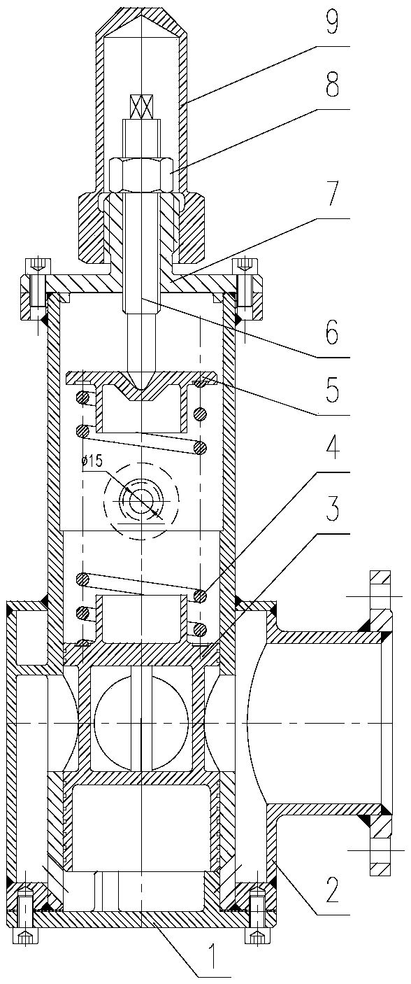
[0021] like figure 2 As shown, a self-operated multi-stage throttling lubricating oil pressure regulating valve consists of a bottom cover 1, a housing 2, a slide valve 3, a spring 4, a gland 5, a screw 6, an upper cover 7, a nut 8, and a cover 9 And related fasteners and seals. The housing 2 of the regulating valve is composed of an inner housing and an outer housing: the outer housing is provided with inlet and outlet flanges and leak port joints, and the bottom of the inner housing is provided with a slanted hole to connect the outlet and the cavity at the bottom of the inner housing. room. The spool valve 3 is set inside the housing 2, the bottom cover 1 is installed at the lower end of the housing 2, and its protruding flange is set inside the housing 2, and becomes a limit for the downward movement of the spool valve 3. A spring 4 is sleeved o...


PUM


Abstract

The invention relates to a self-operated multi-stage throttling lubricating oil pressure regulating valve. A casing is composed of an inner casing body and an outer casing body, the outer casing bodyis provided with an inlet and outlet flange and a leakage opening pipe joint, and the bottom of the inner casing body is provided with an inclined hole to make an outlet and a cavity in the bottom ofthe inner casing body communicated; a sliding valve is sleeved with the casing, a flange extending from a bottom cover is sleeved with the casing and forms a limiting part for the downward movement ofthe sliding valve, a flange extending from the upper side of the sliding valve is sleeved with a spring, and the upper portion of the spring sleeves a flange extending from a gland; the upper end ofthe casing is provided with an upper cover, and a boss with an external thread and an internal thread hole extends from the upper cover; a screw rod is screwed into the internal thread hole of the boss of the upper cover and presses the gland, and the upper portion of the screw rod is fastened and fixed to the upper cover through a nut. By means of the valve, multi-stage throttling of lubricatingoil can be achieved in a limited space, and the vibration noise of a pipeline is effectively reduced; the downstream lubricating oil pressure can be adjusted online, and setting in debugging tests isfacilitated; the damping property of the valve can effectively relieve the drastic fluctuation of regulating the downstream lubricating oil pressure.

Description

technical field [0001] The invention relates to a device for regulating and stabilizing lubricating oil pressure of a marine steam turbine unit, in particular to a multi-stage throttling lubricating oil pressure regulating valve. Background technique [0002] A marine steam turbine unit contains several components that need to be lubricated with oil, such as sliding bearings, couplings, gearboxes, etc. The lubricating oil system of the current marine steam turbine unit is as follows: figure 1 As shown, the lubricating oil produced by the self-contained main oil pump or provided by an external oil source enters the main lubricating pipe, and is depressurized to about 0.15-0.35MPa through the main throttle orifice, and is connected to the main lubricating pipe behind the main throttle orifice. Multiple branch circuits, and sub-throttle orifice plates are installed in the branch circuits to distribute the lubricating oil flow for each oil-using component. [0003] The lubrica...

Claims


Application Information

Patent Timeline
Patent Type & Authority Applications(China)
IPC IPC(8): F16K17/30F16K27/04F16K47/02
CPCF16K17/30F16K27/04F16K47/02
Inventor 倪林森张鲲羽李一兴
Owner SHANGHAI MARINE EQUIP RES INST
Why Eureka
Try Eureka