Radiant electrical equipment dehumidifying device and electrical equipment dehumidifying method

A technology for electrical equipment and power circuits, applied in the field of dehumidification, can solve problems such as unfavorable moisture discharge and deformation of insulating shells, and achieve the effect of facilitating moisture discharge

Inactive Publication Date: 2019-01-25
SICHUAN UNIV
View PDF9 Cites 0 Cited by
  • Summary
  • Abstract
  • Description
  • Claims
  • Application Information

AI Technical Summary

Problems solved by technology

[0003] The main purpose of the present invention is to provide a radiation-type electrical equipment dehumidification device and an electrical equipment dehumidification method to solve the problem of dehumidification of electrical equipment with metal conductors with an insulating shell and a relatively complicated internal structure in the prior art. The internal blowing method will cause deformation of the insulating shell and is not conducive to the problem of moisture discharge

Method used


Image

  • Radiant electrical equipment dehumidifying device and electrical equipment dehumidifying method
  • Radiant electrical equipment dehumidifying device and electrical equipment dehumidifying method
  • Radiant electrical equipment dehumidifying device and electrical equipment dehumidifying method

Examples


Embodiment Construction

[0027] In order to make the object, technical solution and advantages of the present invention clearer, the present invention will be further described in detail below in conjunction with the embodiments and accompanying drawings.

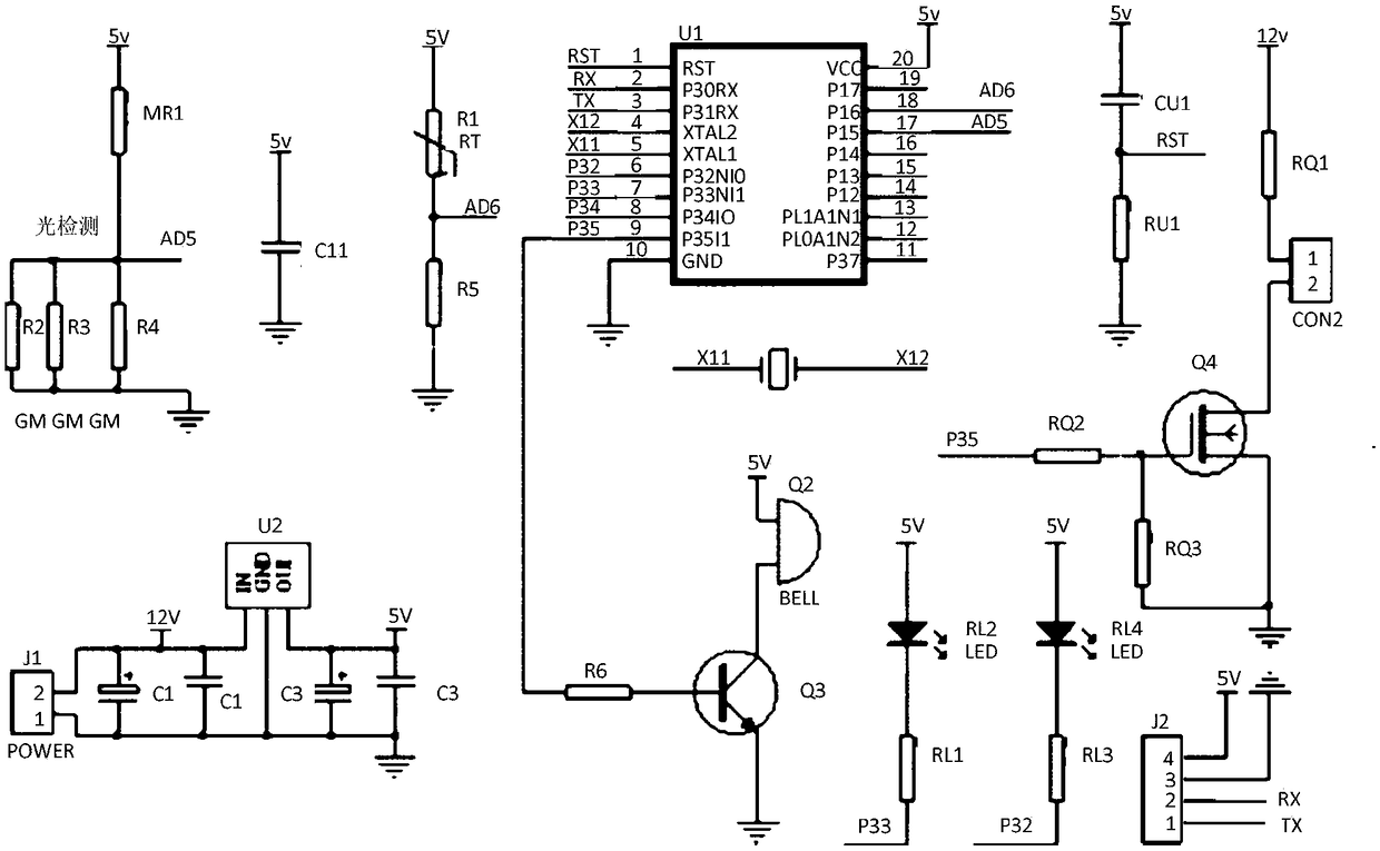
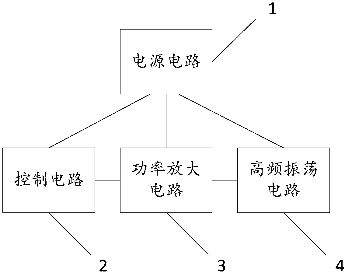
[0028] Such as figure 1 As shown, the radiation-type electrical equipment dehumidification device provided by the embodiment of the present invention includes a high-frequency oscillation circuit 4 , a power amplifier circuit 3 , a control circuit 2 and a power supply circuit 1 . in:

[0029] The high-frequency oscillating circuit 4 is used to generate a high-frequency oscillating current signal. When the high-frequency oscillating current signal flows through the resonant inductance coil 6 in the high-frequency oscillating circuit 4, the inductance coil 6 generates an alternating electromagnetic field that radiates outward, so that it is alternately The metal conductor 13 in the electrical equipment 12 penetrated by the electromagnetic field gene...


PUM


Abstract

The invention discloses a radiant electrical equipment dehumidifying device and an electrical equipment dehumidifying method. An alternating electromagnetic field is generated by utilizing high-frequency oscillating current signals, metal devices in electrical equipment are made to generate heat under the eddy current effect of the alternating electromagnetic field on the metal devices in the electrical equipment to be dehumidified, and thus dehumidification is realized. According to the dehumidification mode, heat is emitted outwards from the inside of the electrical equipment, deformation ofan insulating housing of the electrical equipment will not be caused, and dampness can be discharged more easily.

Description

technical field [0001] The invention relates to a dehumidification technology, in particular to a radiation-type dehumidification device for electrical equipment and a dehumidification method for electrical equipment. Background technique [0002] There are many ways to dehumidify, such as heating or dehumidifiers. However, the dehumidification of electrical equipment with insulating shells or complex internal structures with metal conductors like air switches has its difficult side. For the dehumidification of electrical equipment with complex structure, if a hair dryer is used to dehumidify it, the plastic shell will be damaged, resulting in deformation and burning of the shell. At the same time, this method of blowing from the outside to the inside generates heat from the outside to the inside, which is not conducive to the discharge of moisture. The dehumidification of equipment installed on site during operation cannot use methods such as hair dryers, which cannot ens...

Claims


Application Information

Patent Timeline
Patent Type & Authority Applications(China)
IPC IPC(8): F26B3/347F26B23/08
CPCF26B3/347
Inventor 周步祥杨安勇陈实张致强袁岳廖敏芳何飞宇杨明通
Owner SICHUAN UNIV
Why Eureka
Try Eureka