Laser time-of-flight (TOF) light radar

A time-of-flight and lidar technology, applied in the field of laser time-of-flight lidar

Inactive Publication Date: 2019-01-25
BRIGHTINTELLIGENCE TECH ZHONGSHAN CO LTD
View PDF9 Cites 6 Cited by
  • Summary
  • Abstract
  • Description
  • Claims
  • Application Information

AI Technical Summary

Problems solved by technology

Avalanche diodes and high-speed counters are expensive components and avalanche diodes re

Method used


Image

  • Laser time-of-flight (TOF) light radar
  • Laser time-of-flight (TOF) light radar
  • Laser time-of-flight (TOF) light radar

Examples


Embodiment 1

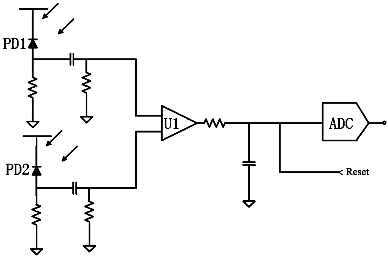
[0021] Embodiment one, such as figure 2 As shown, the single-chip microcomputer is provided with two comparator U1 input terminals, the electrical signal of the first photodiode PD1 is input to one input terminal of the comparator U1 after high-pass filtering, and the electrical signal of the second photodiode PD2 is The signal is input to the second input terminal of the comparator U1 after high-pass filtering. The output terminal of the comparator U1 is low-pass filtered and then connected to the input terminal of the analog-to-digital converter ADC, and the analog-to-digital converter ADC outputs a readable electrical signal.

Embodiment 2

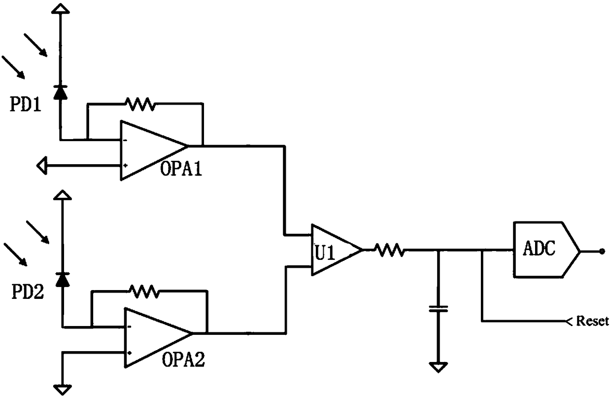
[0022] Embodiment two, such as image 3 As shown, on the basis of the first embodiment, the single-chip microcomputer further includes a first operational amplifier OPA1 and a second operational amplifier OPA2. The electrical signal of the first photodiode PD1 is connected to the input terminal of the first operational amplifier OPA1, and the output terminal of the first operational amplifier OPA1 is connected to one input terminal of the comparator U1. The electrical signal of the second photodiode PD2 is connected to the input terminal of the second operational amplifier OPA2, and the output terminal of the second operational amplifier OPA2 is connected to the two input terminals of the comparator U1. The first operational amplifier OPA1 and the second operational amplifier OPA2 respectively constitute a transimpedance amplifier (Transimpedance amplifier) ​​and then connected to the comparator U1. Using a transimpedance amplifier can fix the bias voltage of the two photodio...

Embodiment 3

[0023] Embodiment three, such as Figure 4 As shown, on the basis of the second embodiment, the single-chip microcomputer further includes a third operational amplifier OPA3 and a fourth operational amplifier OPA4. The output end of the first operational amplifier OPA1 is connected in series with the third operational amplifier OPA3 and then connected to an input end of the comparator U1. The output end of the second operational amplifier OPA2 is connected in series with the fourth operational amplifier OPA4 and then connected to the second input end of the comparator U1. A two-stage amplification method can be used to increase the speed of the two photodiodes: the first stage is still the above-mentioned transimpedance amplifier, and the second stage is composed of the third operational amplifier OPA3 and the fourth operational amplifier OPA4 respectively to form a voltage amplifier. . Due to the amplification effect of the second stage, the transresistance of the first sta...


PUM


Abstract

The invention discloses laser time-of-flight (TOF) light radar. The radar includes a transmitting module and a receiving module. The receiving module includes a first photodiode, a second photodiode and a single chip microcomputer. The single chip microcontroller includes a comparator and an analog-to-digital converter. A signal output end of the single chip microcomputer is connected with a signal input end of the transmitting module. The first photodiode and the second photodiode are arranged in parallel. Electrical signals of the first photodiode and the second photodiode are input to the comparator after high-pass filtering. An output end of the comparator is connected with an input end of the analog-to-digital converter after low-pass filtering. The analog-to-digital converter outputsa readable electrical signal. The radar has the advantages that an analog peripheral circuit of the single chip microcomputer is utilized, construction of the laser time-of-flight light radar can berealized simply with a lower efficiency requirement, thus an assembly structure is greatly simplified, and at the same time, volume and costs are reduced.

Description

technical field [0001] The invention relates to a distance measuring device, in particular to a laser time-of-flight light radar. Background technique [0002] There are many ways to measure optical time-of-flight (TOF), and generally involve complex analog circuits to detect the phase difference between the emitted light pulse and the bounced light pulse. This requires a relatively expensive single-chip process or a large number of discrete analog chips to build the system. The other is to use a very high-speed time-to-digital converter (Time-to-Digital converter TDC) to implement a delay-locked loop (delay-locked loop DLL) circuit. In addition, there are also avalanche diode (APD) pulses and high-speed counters to directly accumulate the time difference of reflected light to calculate the object distance. Avalanche diodes and high-speed counters are expensive components and avalanche diodes require high bias voltages (>15V), which require additional charge pumps or bo...

Claims


Application Information

Patent Timeline
IPC IPC(8): G01S17/36
CPCG01S17/36
Inventor 蔡于颖罗玉辉顾宏广
Owner BRIGHTINTELLIGENCE TECH ZHONGSHAN CO LTD
Why Eureka
Try Eureka