

Interconnected grid line and manufacturing method, applicable solar cell and interconnect mode
A technology of solar cells and solar cells, which is applied in circuits, photovoltaic power generation, electrical components, etc., can solve problems such as high cost, short circuit of cells, and reduction of battery output power, so as to save costs, reduce series resistance, and improve battery performance Effect
- Summary
- Abstract
- Description
- Claims
- Application Information
AI Technical Summary
Problems solved by technology
Method used
Image

Examples
Embodiment 1
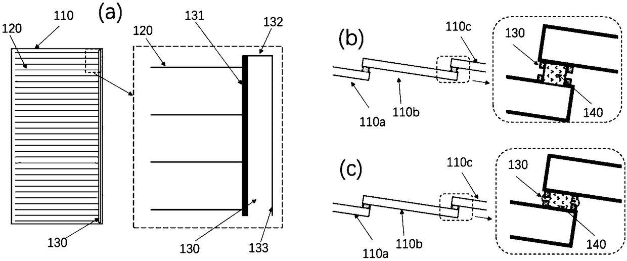
[0033] Such as figure 1 As shown in a, the left side is a schematic diagram of the battery sheet, and the right side is a schematic diagram of the electroplated grid line structure after the interconnection area is enlarged.
[0034] In this embodiment, the electroplated grid wire includes a metal grid wire frame 130 fabricated in the area where the battery slices are interconnected at the long side boundary of the solar battery slice 110 . It includes a main frame 131 parallel to the long side of the battery and connected to one end of the metal sub-gate electrode 120 on the battery sheet, two horizontal sub-frames 132 and a vertical sub-frame 133 . The main frame 131 has a height of about 2-20 μm, preferably 5-12 μm, and a width of 12-300 μm, preferably 80-300 μm. The three sub-frames 132 and 133 have a height of about 2-20 μm, preferably 5-12 μm, and a width of 12-300 μm, preferably 12-45 μm. The length of the lateral sub-frame 132 is about 0.5-3 mm, preferably about 1 m...
Embodiment 2
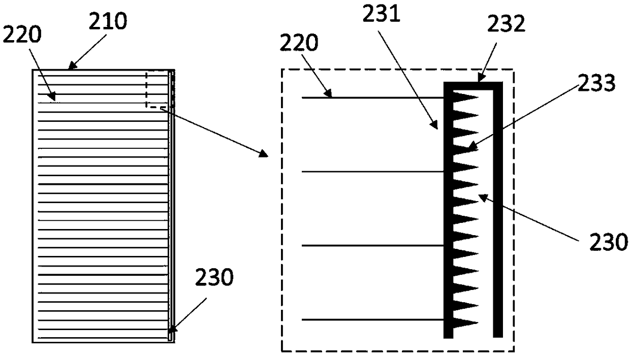
[0039] Such as figure 2 As shown, the left side is a schematic diagram of the battery sheet, and the right side is a schematic diagram of the electroplated grid line structure after the interconnection area is enlarged.
[0040] In this embodiment, the electroplated grid wire includes a metal grid wire frame 230 made in the area where the battery slices are interconnected at the long side boundary of the solar battery slice 210 .
[0041] In this embodiment, the main frame 231 and the secondary frame 232 have the same width, preferably 80-200 μm, and the frame height is about 2-20 μm, preferably 5-12 μm. The length of the lateral sub-frame 132 is about 0.5-3 mm, preferably about 1 mm. The beneficial effect of using a wider sub-frame is that the charge is transmitted through the surrounding frames, not only through the main frame and the conductive glue, which reduces the series resistance and the metal grid wire frame 230 still has a good role in balancing the current when t...
Embodiment 3
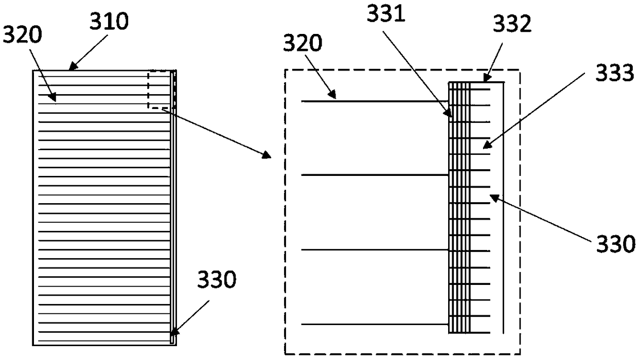
[0045] Such as image 3 As shown, the left side is a schematic diagram of the battery sheet, and the right side is a schematic diagram of the electroplated grid line structure after the interconnection area is enlarged.
[0046] In this embodiment, the electroplated grid wire includes a metal grid wire frame 330 made in the area where the battery slices are interconnected at the long side boundary of the solar battery slice 310 .
[0047] In this embodiment, the sub-frame 332 has a width of 12-300 μm, preferably 12-45 μm, and a height of about 2-20 μm, preferably 5-12 μm. The main frame 331 is a grid-shaped fine grid, and the width of each fine grid line is preferably about 15-45 μm. Using the grid-shaped fine grid as the main frame 331 can reduce the maximum width of the electroplating grid lines and ensure sufficient adhesion of the electroplating grid lines.
[0048] In this embodiment, there is a metal layer 333 with a pattern structure inside the metal grid wire frame 3...
PUM
| Property | Measurement | Unit |
|---|---|---|
| Width | aaaaa | aaaaa |
| Width | aaaaa | aaaaa |
| Length | aaaaa | aaaaa |
Abstract
Description
Claims
Application Information