
Hydraulic control system of hybrid power vehicle and control method thereof

A technology for hydraulic control systems and hybrid vehicles, applied in transmission control, lubrication systems, vehicle components, etc., can solve problems such as unreasonable cooling flow distribution, overheating of drive motors, and insufficient oil supply capacity of oil pumps to ensure overall efficiency. and dynamic performance, the effect of avoiding pressure drop

Pending Publication Date: 2019-01-29
GUANGZHOU AUTOMOBILE GROUP CO LTD
View PDF0 Cites 12 Cited by
  • Summary
  • Abstract
  • Description
  • Claims
  • Application Information

AI Technical Summary

Problems solved by technology

[0003] However, in the prior art, there are few solutions to the above problems. When the clutch or brake does not need to be engaged, the driving motor may overheat due to unreasonable cooling flow distribution.
When the clutch or brake is engaged, affected by factors such as high and low temperature environment, the oil supply capacity of the oil pump is likely to be insufficient, resulting in interruption of vehicle power transmission, excessive speed adjustment time, and excessive impact during the clutch engagement transition process. Stability, as well as problems such as high-speed friction clutch plate wear and burning, seriously affect driving safety and driving experience

Method used


Image

  • Hydraulic control system of hybrid power vehicle and control method thereof
  • Hydraulic control system of hybrid power vehicle and control method thereof
  • Hydraulic control system of hybrid power vehicle and control method thereof

Examples


Embodiment Construction

[0037] The specific implementation manners of the present invention will be further described in detail below in conjunction with the accompanying drawings and embodiments. The following examples are used to illustrate the present invention, but are not intended to limit the scope of the present invention.

[0038] In the description of the present invention, it should be noted that the terms "first" and "second" are used for description purposes only, and should not be understood as indicating or implying relative importance.

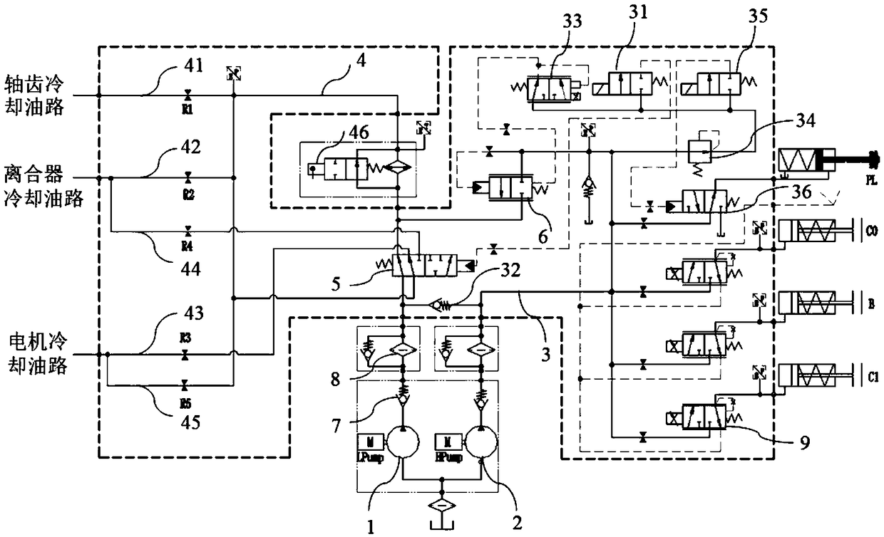
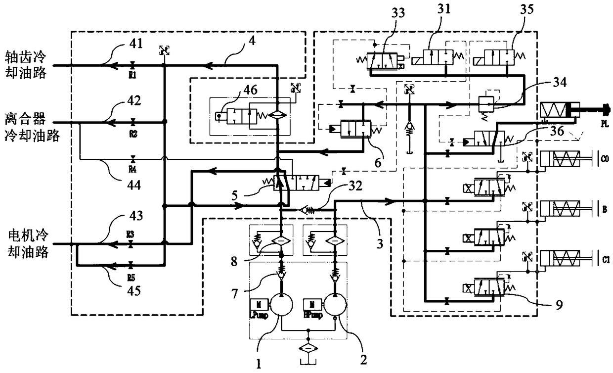
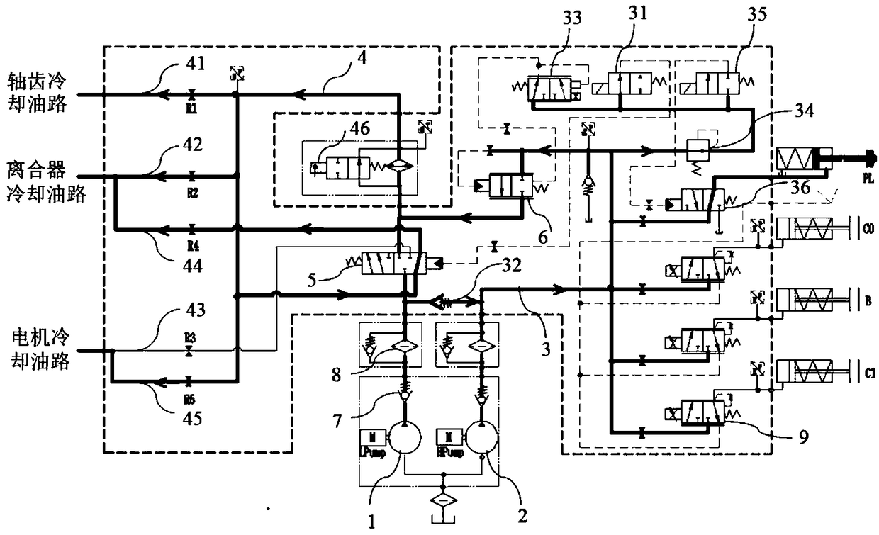
[0039] Please combine figure 1 , figure 2 and image 3 As shown, the hybrid vehicle hydraulic control system of the present invention is schematically shown, including a first oil pressure pump, a second oil pressure pump, a main oil circuit 3, a cooling lubricating oil circuit 4, a reversing valve 5, a pressure regulator For the valve 6 and the first control valve 31 , for example, in this embodiment, the first oil pressure pump is the low-pressur...


PUM


Abstract

The invention relates to the field of hybrid power vehicle control and particularly discloses a hydraulic control system of a hybrid power vehicle and a control method of the hydraulic control systemof the hybrid power vehicle. The hydraulic control system of the hybrid power vehicle comprises a main oil channel, a cooling lubricating oil channel, a reversing valve, a first oil hydraulic pump, asecond oil hydraulic pump communicating with the main oil channel, a pressure adjusting valve connected between the main oil channel and the cooling lubricating oil channel and a first control valve used for controlling the reversing valve to switch the valve position. The reversing valve is located at the first valve position when a clutch or a brake does not need uniting, so that the first oilhydraulic pump is made to communicate with the cooling lubricating oil channel. The reversing valve is located at the second valve position when the clutch or the brake needs uniting, the first oil hydraulic pump and the second oil hydraulic pump are made to be coupled to provide hydraulic oil flow for the main oil channel, and remaining flow is conveyed to the cooling lubricating oil channel. Thehydraulic control system of the hybrid power vehicle reasonably matches the cooling lubricating flow with the hydraulic oil flow of the main oil channel, pressure reduction during uniting of the clutch is avoided, the parts are prevented from being worn and scorched, and the overall efficiency and power performance of the vehicle are ensured beneficially.

Description

technical field [0001] The invention relates to the technical field of hybrid vehicle control, in particular to a hybrid vehicle hydraulic control system and a control method thereof. Background technique [0002] In recent years, gasoline-electric hybrid vehicles have been favored by more and more consumers. The power source of a gasoline-electric hybrid vehicle includes a hybrid motor and an engine, the motor consumes power from the power battery, and the engine consumes fuel. The power and control system of a gasoline-electric hybrid vehicle is a precision component. Under different working modes, the main working and operating components will switch. When the driving motor is used alone as the power source of the vehicle, the clutch or brake of the vehicle does not need to be engaged. At this time, since the driving motor is in a high-speed operating state and the clutch does not need to be engaged by friction, the driving motor needs to be cooled and lubricated. The fl...

Claims


Application Information

Patent Timeline
IPC IPC(8): F16H61/00B60R17/00
CPCF16H61/0025B60R17/00F16H2061/0037Y02T10/62
Inventor 祁宏钟杨洋王川周家豪鲁宜国刘鹏张维明施国飞任晓华赵江灵
Owner GUANGZHOU AUTOMOBILE GROUP CO LTD
Learn More