
Transformer no-load switching inrush current and overvoltage eliminating device

A transformer and overvoltage technology, applied in emergency protection circuit devices, electrical components, etc., can solve the problems of limited withstand voltage margin of insulating materials, decreased measurement accuracy, increased no-load loss of transformers, etc., to save no-load energy consumption, The effect of improving the service life and ensuring the accuracy

Inactive Publication Date: 2019-01-29
HARBIN PATEERN SCI & TECH
View PDF0 Cites 1 Cited by
  • Summary
  • Abstract
  • Description
  • Claims
  • Application Information

AI Technical Summary

Problems solved by technology

Although this is a small probability event, once it occurs, it will often cause people's mental stress and delay the operation of the transformer. Therefore, technical measures must be taken to avoid it.
[0009] 2. The "primary inrush" generated by the air-dropped transformer induces "sympathetic inrush" (sympathetic inrush) in other operating transformers in the power grid and is cut off, causing large-scale power outages
[0010] The airdrop of one transformer caused other operating transformers to be cut off by the protection device, and a large number of loads were cut off. This consequence is extremely serious.
[0011] 3. The large-scale excitation inrush current can sometimes reach ten times or more of the rated current of the transformer, and the electric power generated by it is very destructive to the transformer and other electrical equipment
[0012] 4. The excitation inrush current contains a large number of harmonics, which will cause great harmonic pollution to the power grid, resulting in abnormal operation, vibration, heat generation and increased power loss of a large number of electrical equipment
[0013] 5. The excitation inrush current contains a large DC component, which will cause excessive magnetization to a large number of electromagnetic current transformers, resulting in a significant drop in measurement accuracy, misoperation of relay protection devices, and even irreversible damage to the current transformers
[0014] 6. Existence of excitation inrush current forces a large number of backup power transformers in the power system to operate in a hot standby mode with normal charging to avoid airdrop failure of backup transformers, which increases the no-load loss of a large number of transformers in the power system
[0015] 7. Severe overvoltage is generated when the electric locomotive is over-voltage and phase-splitting, which often causes damage to related equipment. The electric locomotive passes through a power-splitting phase every ten minutes or so, and the main transformer of the locomotive performs power switching here. At this time, the voltage of the main transformer It is the vector sum of induced voltage and phase voltage of neutral line of electric split phase, often triggering serious overvoltage and inrush current, causing damage to electric locomotive, electric split phase and traction substation electrical equipment, affecting the normal operation of the locomotive
[0017] 9. The withstand voltage margin of insulating materials in the UHV power grid is already limited, and it cannot withstand the impact of overvoltage, and the inrush current of the no-load transformer often excites the resonant overvoltage, which makes my country's UHV power grid afraid to use it for a long time. 1000kV side closing no-load transformer, affecting the rapid development of UHV power grid

Method used


Image

  • Transformer no-load switching inrush current and overvoltage eliminating device

Examples


Embodiment Construction

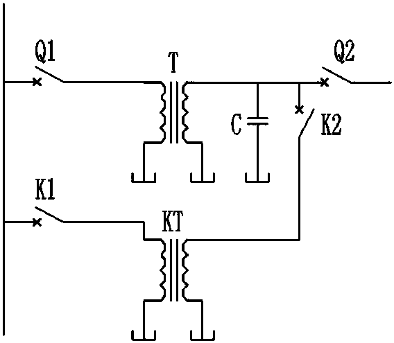
[0037] The circuit diagram of transformer no-load switching inrush current and overvoltage elimination device is to add control transformer KT, high voltage control switch K1 and low voltage control switch K2 on the basis of the original main circuit (including high voltage main switch Q1, main transformer T and low voltage main switch Q2) and low-voltage capacitor bank C, their connections are as follows: the incoming line of K1 is connected to the high-voltage bus, the outgoing line of K1 is connected to the high-voltage side of KT, the low-voltage side of KT is connected to the incoming line of K2, and the outgoing line of K2 is connected to the low-voltage side of T On the side, the low-voltage capacitor bank C is connected between the three phases of the low-voltage side of T.

[0038] The KT, K1, and K2 loops of the device constitute a circuit that eliminates the "switch pre-breakdown phenomenon". Before the main switch Q1 is closed, the loop is connected, and K2 is closed ...


PUM


Abstract

The invention relates to a transformer no-load switching inrush current and overvoltage eliminating device, which belongs to the field of electrical equipment and electrical engineering, can be applied to air-drop transformer at a power plant or transformer substation, and shows the important role played by the device in safe and stable operation of a power grid in the case of an ultrahigh-voltagepower grid in particular. The transformer no-load switching inrush current and overvoltage eliminating device enables equipment such as a power transformer to be free from mechanical and electrical impact, can improve the service life and also greatly improves the life of a main switch at the same time.

Description

technical field [0001] The invention relates to a transformer no-load switching inrush current and overvoltage elimination device, which belongs to the field of electrical equipment and electrical engineering, and can be used for air-dropping transformers in power plants or substations, especially in the case of UHV power grids, which shows that the device is safe for the power grid important role in stable operation. Background technique [0002] The total capacity of the transformers in the power grid can be more than 4 times the total capacity of the generators, and their total harmonic current is very large, which can reach 1% to 2% of the sum of the rated currents of all generators, becoming an important source of background harmonics in the power grid . [0003] A large number of power transformers in the power grid will generate inrush currents and resonant overvoltages equivalent to tens of times the rated current when they are switched on at no-load; and overvoltag...

Claims


Application Information

Patent Timeline
IPC IPC(8): H02H7/04
CPCH02H7/04
Inventor 潘家忠李电元李天昊
Owner HARBIN PATEERN SCI & TECH
Learn More