Oriented pyrolysis reactor based on ray heating

A technology of pyrolysis reactor and reactor, which is applied in the preparation of liquid hydrocarbon mixture, special carbonization, coking oven, etc., can solve the problems of uneven heat exchange, complex reactor structure, and easy blockage of pipelines, etc. Low ash content, fast and efficient pyrolysis, and reliable operation

Inactive Publication Date: 2019-02-01
SHENYANG INSTITUTE OF CHEMICAL TECHNOLOGY
View PDF8 Cites 3 Cited by
  • Summary
  • Abstract
  • Description
  • Claims
  • Application Information

AI Technical Summary

Problems solved by technology

However, the structure of the reactor is complicated, and it is easy to block ...

Method used


Image

  • Oriented pyrolysis reactor based on ray heating
  • Oriented pyrolysis reactor based on ray heating
  • Oriented pyrolysis reactor based on ray heating

Examples


Embodiment 1

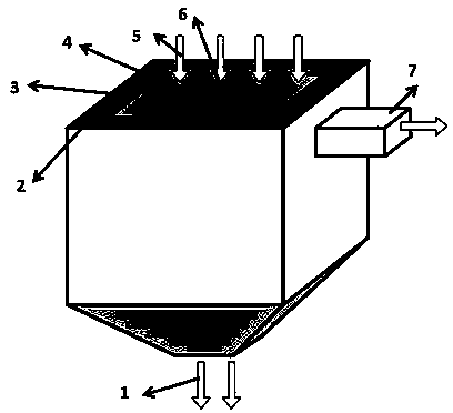
[0039] This embodiment is the intermittent pyrolysis of 5mm waste tire particles, such as figure 1As shown, the directional pyrolysis reactor includes a semi-coke discharge port 1, a thermal insulation and reflection layer 2, a ray emitting source 3, a ray heating chamber 4, a pyrolysis sample feed port 5 and a pyrolysis gas discharge port 7, wherein the The above-mentioned ray heating chamber 4 is also provided with a pyrolysis product channel 6, the wall of the pyrolysis product channel 6 is a plate structure with holes, and the ray emitting source 3 is an infrared emitter. 5mm waste tire particles are evenly filled around the pyrolysis product channel 6, and the upper part of the ray heating chamber 4 is sealed. Turn on the ray emitting source 3, the infrared ray quickly heats the external waste tire particles, and the pyrolysis reaction starts. The pyrolysis gas phase product enters the pyrolysis product channel 6 through the material bed 8, and finally collects into the ...

Embodiment 2

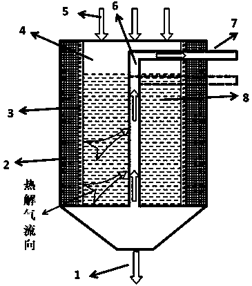
[0041] The present embodiment is the continuous pyrolysis of 5mm Fushun oil shale particles, such as figure 1 As shown, the directional pyrolysis reactor includes a semi-coke discharge port 1, a thermal insulation and reflection layer 2, a ray emitting source 3, a ray heating chamber 4, a pyrolysis sample feed port 5 and a pyrolysis gas discharge port 7, wherein the The above-mentioned ray heating chamber 4 is also provided with a pyrolysis product channel 6, the walls of the pyrolysis product channel 6 are parallel and spaced louver structures, and the ray emitting source 3 is a microwave emitter. The 5mm Fushun oil shale particles are continuously transported into the ray heating chamber 4 and evenly filled around the pyrolysis product channel 6 . Microwaves rapidly heat the oil shale particles, and the pyrolysis reaction begins. The pyrolysis gas phase product enters the pyrolysis product channel 6 through the material bed 8, and finally collects into the pyrolysis gas dis...


PUM


Abstract

The invention discloses an oriented pyrolysis reactor based on ray heating, and relates to a pyrolysis reactor. The reactor device comprises a semi-coke outlet (1), a heat insulation and reflection layer (2), a ray emission source (3), a ray heating chamber (4), a pyrolysis sample inlet (5), a pyrolysis gas outlet (7) and a pyrolysis product channel (6) which is arranged in the ray heating chamber; and ray heating is used to achieve rapid and efficient pyrolysis of low-order fossil energy, renewable wastes and other materials. A gas flow path for the pyrolysis gas to flow from a high-temperature zone to a low-temperature zone is formed. The reactor has prominent characteristics when used, achieves rapid heating by using rays, achieves rapid heat transfer through improving the gas directionby internal members, reduces secondary reactions, and facilitates the improvement of the yield and the quality of tar through the filtering bed effect of centralized centering output of the gas. Thereactor has the advantages of reliability and easiness in design, reasonable structure, suitableness for various pyrolysis materials, and good industrial amplification prospect, and can be widely promoted and applied.

Description

technical field [0001] The invention relates to a directional pyrolysis reactor based on ray heating, in particular to a pyrolysis reactor. Background technique [0002] With the rapid development of the automobile industry and the transportation industry, the amount of waste tires has increased year by year and has become a new source of solid waste pollution. Therefore, the effective recycling of waste tires is a new topic to realize the recycling of renewable energy. The waste tire pyrolysis process can produce carbon black, oil rich in aromatics and fuel gas with high calorific value, which has high economic and environmental benefits. [0003] At the same time, my country's low-order fossil energy reserves are huge and rich in resources, but the utilization rate is low, resulting in a large waste of resources. It is an important way to solve the energy crisis at present to fully explore the potential value and realize the high value-added utilization of low-level foss...

Claims


Application Information

Patent Timeline
IPC IPC(8): C10B53/07C10G1/10
CPCC10B53/07C10G1/10Y02P20/143
Inventor 许光文王超韩振南程继光
Owner SHENYANG INSTITUTE OF CHEMICAL TECHNOLOGY
Why Eureka
Try Eureka