Lateral powder feeding head for laser cladding

A technology of laser cladding and powder feeding, which is applied in the coating process and coating of metal materials. The composition is uniform and controllable, and the effect of improving the utilization rate

Active Publication Date: 2019-02-01
JIANGSU UNIV
View PDF8 Cites 2 Cited by
  • Summary
  • Abstract
  • Description
  • Claims
  • Application Information

AI Technical Summary

Problems solved by technology

Some of the current powder feeders for laser cladding have the function of powder mixing. Due to the difference in powder strength and density, the powder mixing effect is poor.
Therefore, the most commonly used powder mixing method at present is to mix the powder through a ball mill and then carry out laser cladding. When using this method of powder mixing, different types of powder particles must be close together, otherwise it is difficult to ensure the uniformity of the powder mixing, which will affect the laser. The performance o

Method used


Image

  • Lateral powder feeding head for laser cladding
  • Lateral powder feeding head for laser cladding
  • Lateral powder feeding head for laser cladding

Examples


Embodiment 1

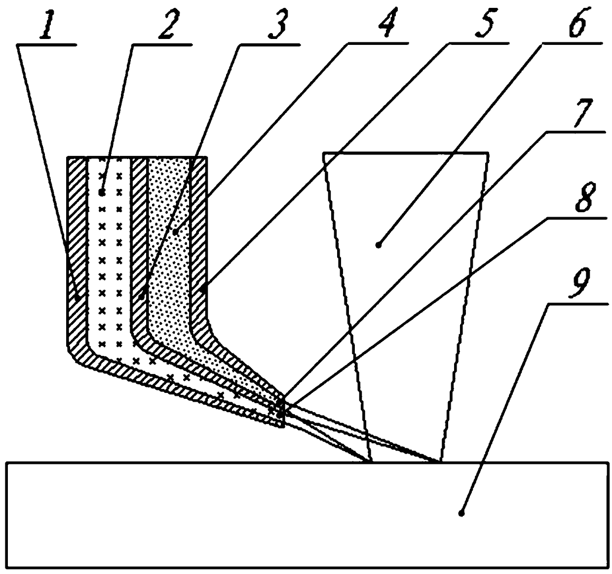
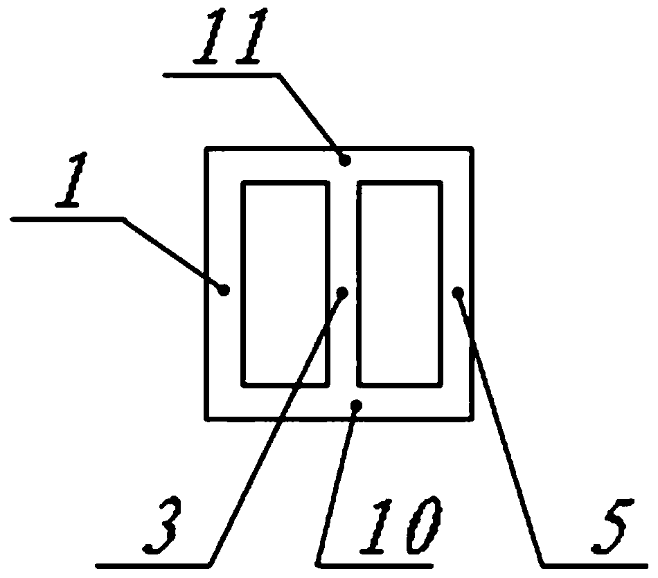
[0016] Cladding a layer of Al with a thickness of 0.5mm on the surface of 45 steel 2 o 3 / TiO 2 Ceramic coating, using a 3000 watt continuous fiber laser, the spot shape of the laser beam 6 is 4mm×2mm, and the inside of the independent cavity is Al 2 o 3 Powder, powder feeding speed is 2cm 3 / s, the carrier gas pressure is 0.15MPa; the second independent chamber is TiO 2 Powder, powder feeding speed is 0.8cm 3 / s, the carrier gas pressure is 0.15MPa; after laser cladding, after testing, Al with a volume ratio of 5:2 and a coefficient of variation of mixing uniformity less than 0.5% was obtained on the surface of 45 steel 2 o 3 / TiO 2 Composite ceramic coating, laser cladding quality is stable.

Embodiment 2

[0018] On the surface of 45 steel, laser 3D printing functionally graded composite parts is used. The material composition near the surface of 45 steel is WC (volume content of 5%) reinforced Mo2FeB2 composite material, which gradually transitions to the WC (volume content of 20%) on the surface. Mo2FeB2 composite material, thickness is 2mm, adopts 3000 watts continuous fiber laser, the light spot shape of laser beam 6 is 4mm×2mm, adopts the mode of layer-by-layer sintering (the first layer, the WC powder is in independent cavity 1, powder feeding speed 0.1cm 3 / min, Mo in independent chamber 2 2 FeB 2 Powder, powder feeding speed is 1.9cm 3 / min, the carrier gas pressure is 0.1MPa; the second layer, the independent chamber 1 contains WC powder, and the powder feeding speed is 0.2cm 3 / min, Mo in independent chamber 2 2 FeB 2 Powder, powder feeding speed is 1.8cm 3 / min, the carrier gas pressure is 0.1MPa; the third layer, the independent chamber 1 contains WC powder, and...


PUM


Abstract

The invention relates to the field of non-traditional machining, in particular to a lateral powder feeding head for laser cladding. The lateral powder feeding head for laser cladding is formed by a left wall, a clapboard, a right wall, a front wall and a back wall, wherein the clapboard divides the powder feeding head into an independent cavity I and an independent cavity II with two rectangular cross sections; the lower ends of the two independent cavities are reduced to form two rectangular powder nozzle I and powder nozzle II; the end surfaces of the powder nozzle I and the powder nozzle IIare located on the same vertical plane; the independent cavity I and the independent cavity II feed powder through carrier gases and have the same internal powder feeding pressure; the powder nozzleI and the powder nozzle II spray various powder at the same time, the powder is radiated and melted through a laser beam so as to arrive at the surface of a workpiece, and the covering areas of the sprayed powder arriving at the surface of the workpiece coincide exactly; the cross section of the laser beam is in a rectangular shape, and the shape and the size of the laser beam and the shape and the size of the powder arriving at the surface of the workpiece are identical and coincide in positions; and the laser beam is firstly acted on the powder sprayed through the powder nozzle I and the powder nozzle II and is then acted on the surface of the workpiece.

Description

technical field [0001] The invention relates to the field of special processing, in particular to a side powder feeding head for laser cladding. Background technique [0002] Laser cladding can obtain a protective layer with specific properties on the surface of metal workpieces, which can greatly improve the wear resistance, corrosion resistance, and hydrogen embrittlement resistance of the workpiece, and can greatly improve the service life of key components. In some applications, it is necessary to mix different types of powders for laser cladding. Some of the current powder feeders for laser cladding have the function of powder mixing. Due to the difference in strength and density of the powder, the powder mixing effect is poor. Therefore, the most commonly used powder mixing method at present is to mix the powder through a ball mill and then carry out laser cladding. When using this method of powder mixing, different types of powder particles must be close together, ot...

Claims


Application Information

Patent Timeline
IPC IPC(8): C23C24/10
CPCC23C24/10
Inventor 戴峰泽霍坤
Owner JIANGSU UNIV
Why Eureka
Try Eureka