Rotor blade surface dynamic pressure measuring system and method based on phase locking method

A dynamic pressure and measurement system technology, applied in force/torque/work measuring instruments, measuring devices, instruments, etc., can solve the problems of data not corresponding to the rotor phase, unstable speed, signal distortion, etc., and achieve accurate phase locking and recording function, to ensure the accuracy of sampling, to ensure the effect of signal-to-noise ratio

Active Publication Date: 2019-02-01
NORTHWESTERN POLYTECHNICAL UNIV
View PDF10 Cites 9 Cited by
  • Summary
  • Abstract
  • Description
  • Claims
  • Application Information

AI Technical Summary

Problems solved by technology

Moreover, most technologies are difficult to solve the problems of signal distortion and electromagnetic interference in the process of signal transmission and conversion. Therefore, they only stay at the stage of theoretical research and are difficult to apply to engineering practice.
At the same time, since the rotational speed of the rotating machinery cannot be kept absolutely stable, the relationship between the rotor blade phase and time cannot be kept absolutely periodic, and the collected data often cannot accurately correspond to the rotor phase.
However, domestic dynamic pressure measurement systems seldom take into account the problem of speed instability
This problem can be solved with the help of the phase locking method. The current phase locking method used in China is often based on the relative coordinate system, and it is still unable to obtain the precise correspondence between the collected data and the absolute coordinate system, and cannot accurately record the phase and the relative coordinate system. corresponding pressure
This has an impact on the results of subsequent data analysis and processing, resulting in the inability to accurately extract the data collected by the sensor at a certain phase of the blade

Method used


Image

  • Rotor blade surface dynamic pressure measuring system and method based on phase locking method
  • Rotor blade surface dynamic pressure measuring system and method based on phase locking method
  • Rotor blade surface dynamic pressure measuring system and method based on phase locking method

Examples


Embodiment Construction

[0013] In order to make the purpose, technical solutions and advantages of the embodiments of the present invention clearer, the present invention will be further described in detail below in conjunction with the embodiments and accompanying drawings. Here, the exemplary embodiments and descriptions of the present invention are used to explain the present invention, but not to limit the present invention.

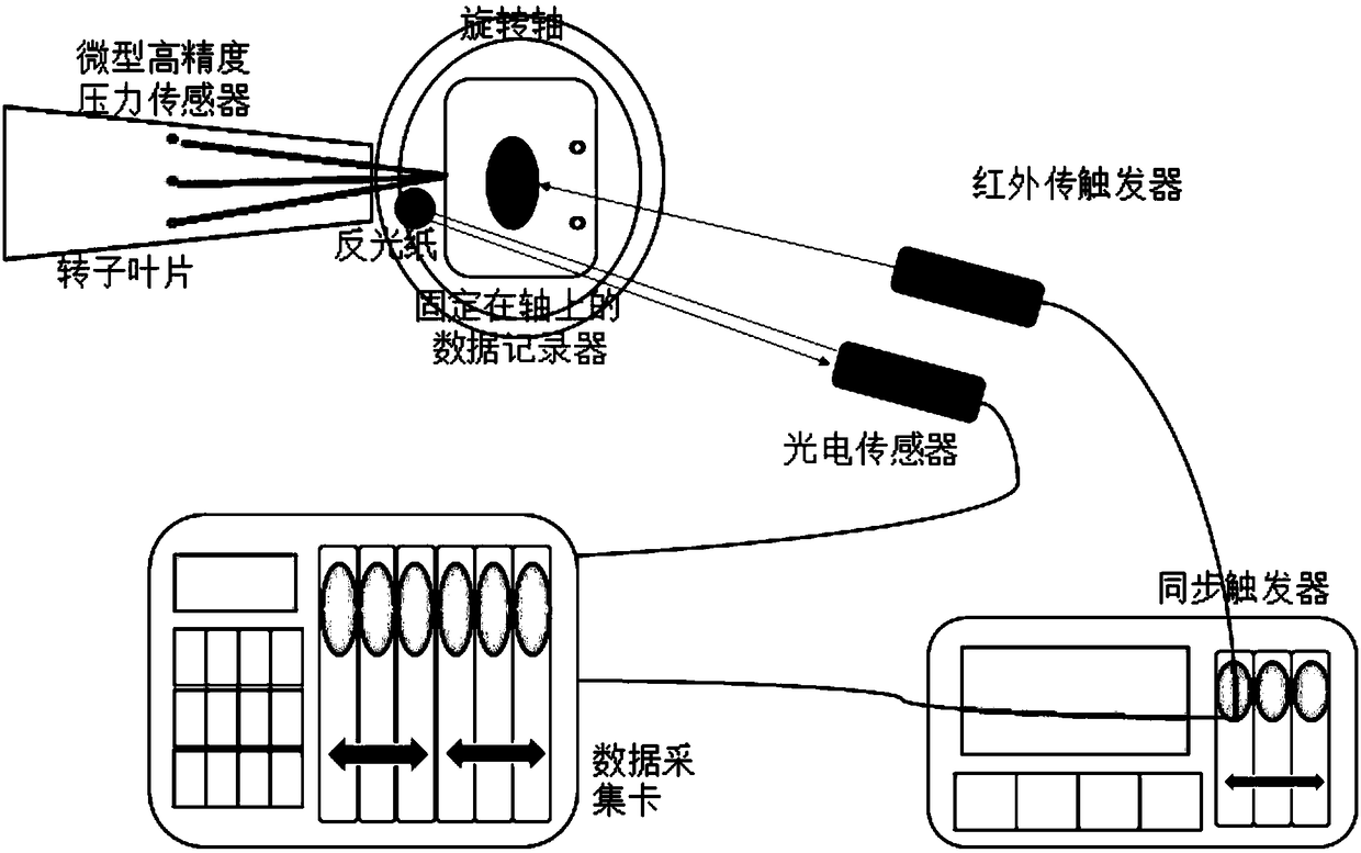
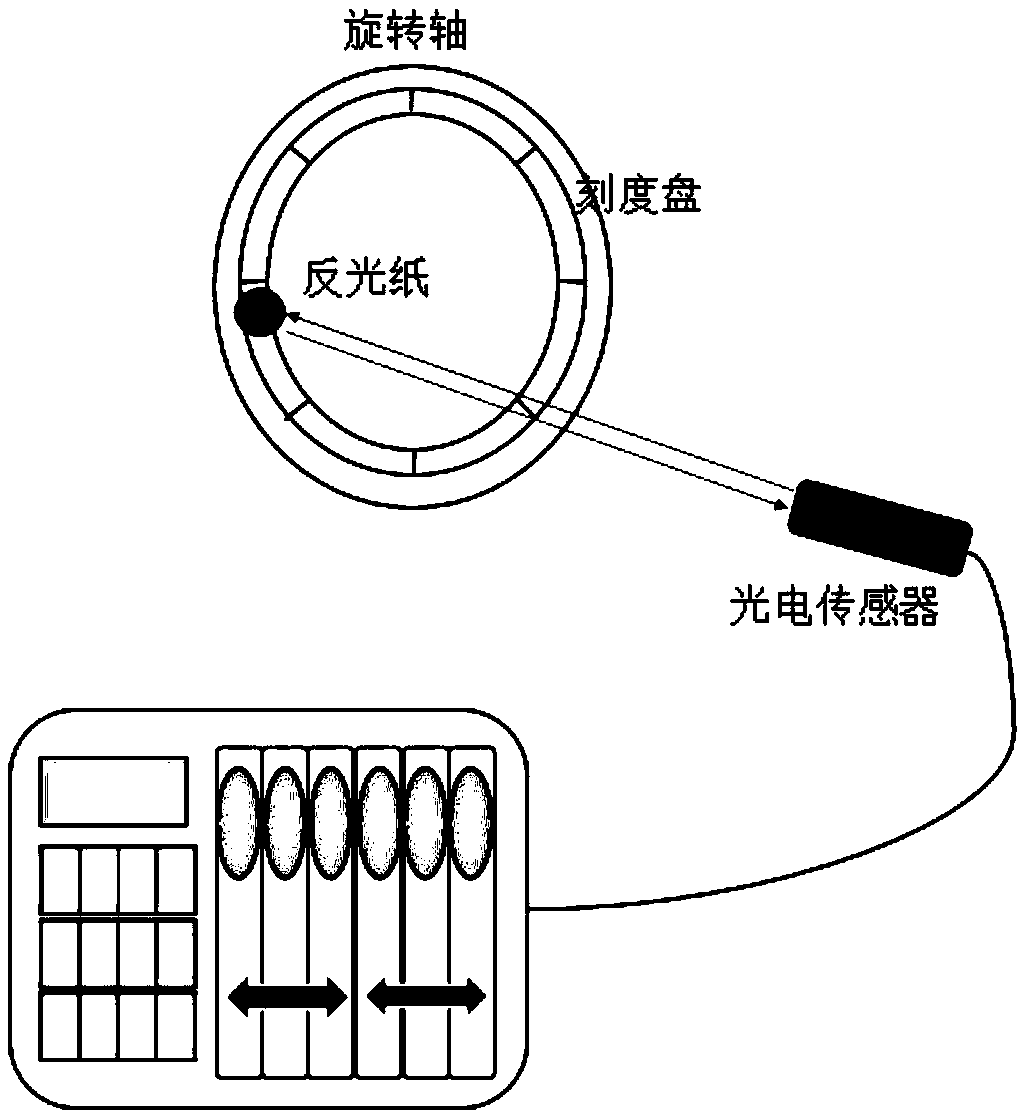
[0014] The rotor blade surface dynamic pressure measurement system based on the phase locking method provided by the present invention includes a synchronous trigger device, a phase measurement recording system and a dynamic pressure measurement recording system, see figure 1 . The synchronous trigger device includes a synchronous trigger and an infrared laser. The phase recording system includes a dial, a reflector, a high-sensitivity photoelectric sensor, and a data acquisition card, see figure 2 . The dynamic pressure measurement and recording system includes a high-...


PUM


Abstract

The invention relates to a rotor blade surface dynamic pressure measuring method and system based on a phase locking method. The measuring system designed by the measuring method comprises a high-sensitivity photoelectric sensor, a micro dynamic pressure sensor, an infrared trigger, a data recorder fixed to a rotating shaft, a data acquisition card and other devices. The rotor blade surface dynamic pressure measuring method and system based on the phase locking method can overcome the defects of an existing device, sampling frequency of the designed system is only related to sampling frequencyof the sensor and the data recorder, and the limitation on the sampling frequency caused by a data transmission mode is avoided. As a data transmission line is adopted for data transmission, noise interference can be avoided to the greatest extent, and the accuracy of acquisition data can be ensured; and meanwhile, the instability of rotating speed is considered, the phase locking method is adopted, so that the rotor surface dynamic pressure is accurately recorded, a rotor blade rotating phase is recorded in an absolute coordinate system, and the pressure information of the blade surface at acertain phase is accurately extracted.

Description

technical field [0001] The invention relates to an experimental method for measuring dynamic pressure on the rotor blade surface of a rotary machine, and more specifically, the method is based on a phase locking method to realize the measurement of the dynamic pressure on the rotor blade surface. Background technique [0002] As an important energy conversion and power transmission device, impeller machinery is widely used in various fields of the national economy, from electric fans in daily life to various forms of blowers and water pumps used in industrial production, and in the aerospace field. Compressors, turbines, etc. all belong to the category of turbomachinery. The flow field inside the turbomachinery is essentially a complex three-dimensional, viscous, unsteady flow field, and the state of any point in space changes with time. The pressure distribution on the rotor blade surface reflects many details of the flow field, and its dynamic changes often produce more p...

Claims


Application Information

Patent Timeline
IPC IPC(8): G01L5/00
CPCG01L5/0061
Inventor 高丽敏郑天龙葛宁杨冠华高天宇吴锋
Owner NORTHWESTERN POLYTECHNICAL UNIV
Why Eureka
Try Eureka