Heat exchanger diagnosing method

A technology for heat exchangers and process controllers, which is applied in the field of diagnosis of the degree of dirtiness of heat exchangers, and can solve problems such as reduced heat transfer efficiency

Active Publication Date: 2019-02-01
SAMSON AG
View PDF14 Cites 2 Cited by
  • Summary
  • Abstract
  • Description
  • Claims
  • Application Information

AI Technical Summary

Problems solved by technology

[0004] During long-term use of the heat exchanger, clogging of the heat exchanger channels due to dirt and lime deposits, etc., resulting in an undesired reduction in heat transfer efficiency

Method used


Image

  • Heat exchanger diagnosing method
  • Heat exchanger diagnosing method

Examples


Embodiment Construction

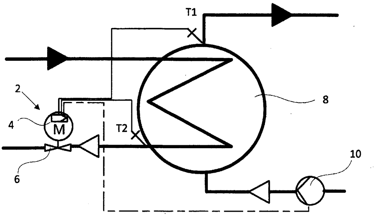
[0044] figure 1 A schematic diagram of a district heating application utilizing a process controller 4 and a controllable regulating valve 6 controlled by the process controller 4 is shown. The regulating valve 6 is connected to the heat exchanger 8 and obtains the initial flow temperature T1 of the user circuit and the return flow temperature T2 of the piping circuit as measurement parameters. Optionally, a pump 10 is connected to the process control drive 2 in the consumer circuit, which provides further control possibilities. The process controller 4 adjusts the regulating valve 6 to the theoretical heat transfer efficiency. The mass flow in the piping circuit required for the theoretical heat transfer efficiency is analyzed as a measure for the degree of fouling of the heat exchanger 8 . exist figure 1 In the example figure, the process control driving mechanism 2 is used in combination with the regulating valve 6 for heating control of the initial flow temperature of t...


PUM


Abstract

The invention relates to a heat exchanger diagnosing method. The primary mass flow of the flowing medium flowing through a heat exchanger (8, 18) is regulated by a regulating valve (6, 16) controlledby a process controller (4, 14), wherein the valve position values provided by the process controller (4, 14) for the regulating valves (6, 16) are obtained and stored. The heat exchanger diagnosing method is characterized in that the valve position value for the regulating valve (6, 16) is recorded during the recording period, so that in at least one sequence of measurement results, the valve position value assigned to a periodic observation period is stored, wherein the observation period reflects that in the same time period of one year, the dirty degree of heat exchanger (8,18) is diagnosed by analyzing a position value of the at least one sequence of measurement results throughout the recording period when a deviation of the stored measurement value from a reference value assigned tothe sequence of measurement results is greater than a predetermined deviation from the reference value.

Description

technical field [0001] The invention relates to a method for diagnosing the degree of contamination of a heat exchanger, wherein the primary-side mass flow of the flow medium flowing through the heat exchanger is regulated by means of a regulating valve which is regulated by a process controller, wherein the process controller provides The valve position value for the regulating valve is obtained and stored. Background technique [0002] DE 20 2014 202 478 A1 discloses a method and a device for the diagnosis of a heating installation with at least one heat exchanger, where the time required for the flow medium to heat up at a defined temperature is longer than a defined time and / or when the flow through the heat exchanger A notification is issued and / or stored when the heating of the specified mass flow of the flowing medium remains below a predetermined temperature difference. For this purpose, the temperature difference between the inlet temperature and the return tempera...

Claims


Application Information

Patent Timeline
Patent Type & Authority Applications(China)
IPC IPC(8): G01M99/00
CPCG01M99/002F24D10/003F24D19/1006F28F27/00F28G15/003Y02E20/14Y02B30/17
Inventor R·施瓦布
Owner SAMSON AG
Why Eureka
Try Eureka