Lateral pressure-type equipment special for cleaning high-rise glass curtain wall

A glass curtain wall and special equipment technology, applied in the field of cleaning, can solve the problems of short continuous working time, high power consumption, high equipment cost, etc., achieve the effect of cleaning without dead ends and reducing the load of equipment

Inactive Publication Date: 2019-02-05
LANZHOU UNIVERSITY OF TECHNOLOGY +1
8 Cites 7 Cited by

AI-Extracted Technical Summary

Problems solved by technology

At present, there is no available high-rise glass curtain wall cleaning equipment on the market. Patent CN 1586384 A proposes a high-rise glass curtain wall cleaning system pulled by a hoist. It adopts a sealing mechanism and a double suction cup mechanism t...

Method used

Due to the traction of cleaning box and wind box, frame 38 unavoidably overturns, so need counterweight be set on frame 38, and common lead block or cement block are thick and heavy, carry to the roof from ground not very convenient , Therefore, as shown in Figure 1 and Figure 2, frame 38 left tops are provided with counterweight wate...

Abstract

Provided is lateral pressure-type equipment special for cleaning a high-rise glass curtain wall. A rack 38 of the equipment is provided with trundles 2, guiding wheels 34, auxiliary wheels 19 and a balance weight water tank 5 and can move stably among the wall body of the glass curtain wall 33. A cleaning box 22 and a wind power box 25 are hoisted through a hoisting motor 39 and a steel wire ropewinding drum 6; the cleaning box 22 is internally provided with a water pump 48, a brush roller 31, a first-level scraping plate 32 and a second-level scraping plate 23, the wind power box 25 is internally provided with a fan motor 26 and a fan 24, and the equipment can tightly fit the surface of the glass curtain wall 33 to achieve rough cleaning and precise cleaning. Electric power is supplied to the cleaning box 22 and the wind power box 25 through a cable winding drum 15 and a cable 16. The cleaning equipment runs stably, supplies electric power and water constantly, conducts cleaning thoroughly without a dead angle and is applicable to cleaning of the high-rise glass curtain wall, and balance weights are flexible and easy to operate.

Application Domain

Carpet cleanersFloor cleaners +3

Technology Topic

EngineeringWire rope +6

Image

  • Lateral pressure-type equipment special for cleaning high-rise glass curtain wall
  • Lateral pressure-type equipment special for cleaning high-rise glass curtain wall
  • Lateral pressure-type equipment special for cleaning high-rise glass curtain wall

Examples

  • Experimental program(1)

Example Embodiment

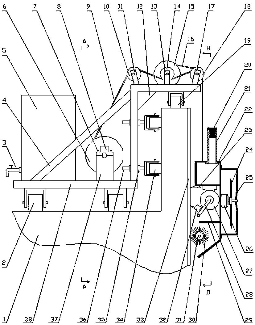
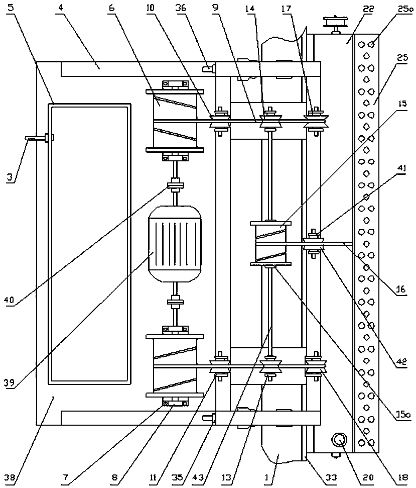
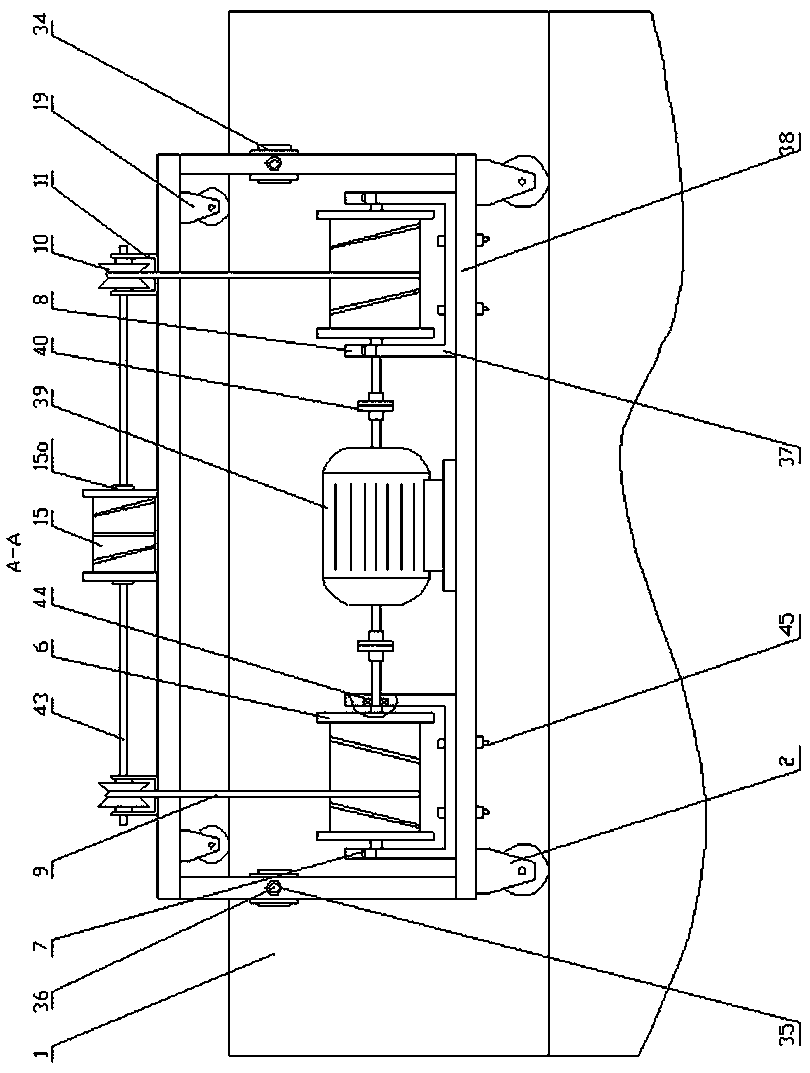
[0010] Such as Figure 1~Figure 5 As shown, the present invention is a special equipment for side-pressing high-rise glass curtain wall cleaning. The frame 38 is in an inverted Z shape, and the diagonal rod 4 is welded between the left and the middle of the frame 38, and between the middle and the right of the frame 38 Welded with reinforced ribs 12, four casters 2 are fixedly installed under the left part of the frame 38, and the casters 2 are placed horizontally on the roof 1. Among the four casters 2, two are universal wheels and the other two are fixed wheels Four guide wheels 34 are fixedly installed on the right side of the middle part of the frame 38 through a limit nut 35 and a screw 36. The guide wheels 34 are close to the inside of the wall of the roof 1, and four auxiliary wheels are fixedly installed under the right part of the frame 38. The wheel 19 and the auxiliary wheel 19 are placed horizontally above the wall of the roof 1. The upper left part of the frame 38 is provided with a counterweight water tank 5, and the lower left side of the counterweight water tank 5 is provided with a drain valve 3, and the middle part of the frame 38 passes bolts The nut assembly 45 is fixed with two reel brackets 37, the two pairs of bearing seats 8 are respectively installed on the upper part of the two reel brackets 37 through the bolt assembly 7. The bearing seat 8 is installed with a bearing 44, and the two wire rope drums 6 are symmetrically installed on the bearing 44 Inside, a wire rope 9 is wound on a wire rope drum 6. The wire rope drum 6 is connected to a hoisting motor 39 through a coupling 40. A pair of rear brackets 11 and a pair of bridges are fixed in turn from left to right on the upper right of the frame 38 Wheel bracket 13 and a pair of front brackets 17, a rear support wheel 10 is installed on the rear bracket 11, a bridge wheel 14 is installed on the bridge wheel bracket 13, a front support wheel 18 is installed on the front bracket 17, a pair of bridge wheels A bridge axle 43 is installed between 14 and a cable reel 15 is fixed in the middle of the bridge axle 43 through a circlip 15a. A cable 16 is wound on the cable reel 15, and a middle support wheel bracket 41 is fixed at the upper right and center of the frame 38 , The middle support wheel 42 is installed on the middle support wheel bracket 41. The outside of the wall of the roof 1 is vertically hoisted with a cleaning box 22 through a wire rope 9. The right side of the cleaning box 22 is fixedly welded with a wind box 25, and the cable 16 bypasses the middle support The washing box 22 and the wind box 25 are connected after the wheel 42.
[0011] Such as Figure 1~Figure 5 As shown, the upper part of the cleaning tank 22 is provided with a water injection port 21, the upper end of the water injection port 21 is equipped with a rubber plug 20, the upper part of the cleaning tank 22 contains water, and two water pump motors 49 are installed symmetrically in the middle. The coupling 27 is connected with the water pump 48. The outlet of the water pump 48 is equipped with a high-pressure water pipe 28. The high-pressure water pipe 28 is connected with a spray pipe 59 through a three-way joint 59. The two ends of the spray pipe 59 are equipped with pipe plugs 60. The right end of the cleaning box 22 The roller brush motor 57 is fixed inside, and the shaft end of the roller brush motor 57 is connected with a driving shaft coupling 50. One end of the driving shaft 51 is connected with the driving shaft coupling 50, and the other end passes through the active bearing seat 52 outside the right end of the cleaning box 22 After connecting with the driving wheel 53, the driving wheel 53 is matched with the driven wheel 55 through the belt 54. The driven wheel 55 is mounted on the roller brush shaft 56. The roller brush shaft 56 is sleeved in the driven bearing seat 46, and the driven bearing seat 46 is fixed in Outside the right end of the cleaning box 22, the brush roller 31 is fixed and sleeved on the roller brush shaft 56, and the bristles 30 are planted on the outer surface of the brush roller 31. A primary scraper 32 is installed on the brush roller 31 by means of screws 47. Secondary scraper 23.
[0012] Such as Figure 1~Figure 4 As shown, four fan motors 26 are installed inside the wind box 25, each fan motor 26 is fixed with a fan 24 in the middle of the shaft, and the shaft end is sleeved in the right shell of the wind box 25, and the right side of the wind box 25 Four fan-shaped wind windows 25b are processed on the shell, and dozens of ventilation holes 25a are processed on the surrounding shell.
[0013] In the following, the present invention will be further explained in conjunction with the accompanying drawings: figure 1 with figure 2 As shown, the side pressure type high-rise glass curtain wall cleaning special equipment of the present invention is mainly composed of casters 2, frame 38, guide wheels 34, auxiliary wheels 19, counterweight water tank 5, hoisting motor 39, wire rope reel 6, cable reel The cylinder 15, the cleaning box 22 and the wind box 25 are composed. Among them, the cleaning box 25 is mainly composed of a water injection port 21, a primary scraper 32, a secondary scraper 23, a water pump motor 49, a water pump 48, a water spray pipe 59 and a brush roller 31, and is used to clean the glass curtain wall 33; the wind box 25 It is mainly composed of a fan motor 26 and a fan 24 for providing wind power to make the cleaning box 22 and the glass curtain wall 33 closely fit.
[0014] Such as figure 1 As shown, the frame 38 is in the shape of an inverted Z, the diagonal rod 4 is welded between the left and the middle of the frame 38, and the reinforcing rib 12 is welded between the middle and the right of the frame 38. Four casters 2 are fixedly installed under the left part of the frame 38, and the casters 2 are placed horizontally on the roof 1 of the building. Among the four casters 2, two are universal wheels and the other two are fixed wheels to facilitate the turning of the frame 38. Four guide wheels 34 are fixedly installed on the right side of the middle part of the frame 38 through a limit nut 35 and a screw 36, and the guide wheels 34 are close to the inner side of the wall of the roof 1. Four auxiliary wheels 19 are fixedly installed under the right part of the frame 38, and the auxiliary wheels 19 are placed horizontally above the wall of the roof 1. By adjusting the limit nut 35, the auxiliary wheel 19 can be exactly in the upper center of the wall. The casters 2 ensure that the frame 38 walks and stays smoothly on the roof 1. The guide wheels 34 and auxiliary wheels 19 cooperate to ensure that the frame 38 walks close to the wall of the roof 1, providing a stable running track for the cleaning of the glass curtain wall 33 , So as to ensure that the cleaning is not missed or scratched.
[0015] Such as image 3 As shown, two reel brackets 37 are fixed on the middle of the frame 38 through bolt and nut assemblies 45, two pairs of bearing seats 8 are respectively mounted on the two reel brackets 37 through bolt assemblies 7, and bearings 44 are installed in the bearing seats 8. Two steel wire rope drums 6 are symmetrically installed in the bearing 44, and a steel wire rope 9 is wound on the steel wire rope drum 6. Combine figure 2 , The wire rope drum 6 is connected to the hoisting motor 39 through a coupling 40. The hoisting motor 39 is a forward and reverse motor, which can drive the wire rope drum 6 to rotate forward and backward after being started, thereby releasing or retracting the wire rope 9.
[0016] Such as figure 1 As shown, a pair of rear brackets 11, a pair of bridge wheel brackets 13, and a pair of front brackets 17 are sequentially fixed on the upper right part of the frame 38 from left to right. The rear bracket 11 is equipped with a rear support wheel 10 and a bridge wheel bracket. A bridge wheel 14 is installed on 13 and a front support wheel 18 is installed on the front bracket 17. Combine figure 2 A bridge wheel shaft 43 is installed between the pair of bridge wheels 14, a cable drum 15 is fixed in the middle of the bridge wheel shaft 43 through a circlip 15 a, and the cable drum 15 is wound around the cable 16. A middle supporting wheel bracket 41 is fixed at the upper center of the right part of the frame, and a middle supporting wheel 42 is installed on the middle supporting wheel bracket 41.
[0017] Such as figure 1 As shown, the outside of the wall of the roof 1 is vertically hoisted with a cleaning box 22 through a steel wire 9, and the right side of the cleaning box 22 is fixedly welded with a wind box 25. The cable 16 bypasses the middle support wheel 42 and then connects to the cleaning box 22 and the wind box 25.
[0018] Due to the traction of the cleaning box and the wind box, the frame 38 will inevitably be overturned. Therefore, it is necessary to set a counterweight on the frame 38. The ordinary lead block or cement block is relatively thick and is not convenient to transport from the ground to the roof. Therefore, Such as figure 1 with figure 2 As shown, a counterweight water tank 5 is provided on the upper left of the frame 38, and the counterweight tank is filled with water to serve as a counterweight to ensure that the frame 38 is stable and does not tip over. After the operation is completed, the water in the counterweight water tank 5 is emptied through the water discharge valve 3 provided at the lower left side of the counterweight water tank 5.
[0019] Such as figure 1 As shown, the upper part of the cleaning tank 22 is provided with a water injection port 21, and the upper end of the water injection port 21 is equipped with a rubber plug 20. The upper sealing part of the cleaning tank 22 can be used for holding water. Such as Figure 5 As shown, two water pump motors 49 are symmetrically installed in the middle of the cleaning tank 22. The water pump motors 49 are connected to the water pump 48 through a cover coupling 27. The water outlet of the water pump 48 is equipped with a high-pressure water pipe 28, which is connected through a three-way joint 58. There is a spray pipe 59, and two ends of the spray pipe 59 are equipped with pipe plugs 60. A roller brush motor 57 is fixed inside the right end of the cleaning box 22. The shaft end of the roller brush motor 57 is connected to a drive shaft coupling 50. One end of the drive shaft 51 is connected to the drive shaft coupling 50, and the other end passes through the outer right end of the cleaning box 22 The driving bearing seat 52 is connected to the driving wheel 53, and the driving wheel 53 is matched with the driven wheel 55 via the belt 54. The driven wheel 55 is installed on the roller brush shaft 56. The roller brush shaft 56 is sleeved in the driven bearing seat 46. The driven bearing The seat 46 is fixed on the outside of the right end of the cleaning tank 22. by figure 1 with Figure 5 It can be seen that the brush roller 31 is fixedly sleeved on the roller brush shaft 56 and the bristles 30 are planted on the outer surface of the brush roller 31. A primary scraper 32 is installed above the brush roller 31 by means of screws 47, and a secondary scraper 23 is fixed above the primary scraper 32. By adjusting the flow rate in the high-pressure water pipe 28, the water spray amount of the water spray pipe 59 can be adjusted to adapt to different cleaning operating conditions.
[0020] Such as figure 1 As shown, four fan motors 26 are installed inside the wind box 25, and a fan 24 is fixed in the middle of each fan motor 26, and the shaft end is sleeved in the right side shell of the wind box 25. Such as Figure 4 As shown, the right side shell of the wind box 25 is processed with four fan-shaped wind windows 25b, and dozens of ventilation holes 25a are processed on the surrounding shell. When the fan motor 26 drives the fan 24 to rotate at a high speed, a large amount of high-pressure airflow is discharged from the fan-shaped wind window 25b, thereby generating a leftward thrust on the cleaning box 22, so that the cleaning box 22 is closely attached to the surface of the glass curtain wall 33. The fan motor 26 is a speed-regulating motor, and when the rotation speed changes, the thrust received by the cleaning box 22 also changes.
[0021] The application of the present invention is divided into the following five steps:
[0022] Installation—Transport a special equipment for cleaning the side-pressure high-rise glass curtain wall of the present invention to the roof of the building where the glass curtain wall needs to be cleaned. Connect a plastic water supply pipe from the water room on the top floor, the length of which should be able to reach both ends of the glass curtain wall 33. Place the frame 38 on the inner side of the wall where the glass curtain wall 33 is located, adjust the limit nut 35 so that the guide wheel 34 is close to the inner side of the wall, and the auxiliary wheel 19 is in the upper center of the wall. Pour water into the counterweight water tank 5, about 5 cm away from the upper edge of the counterweight water tank 5. The wire rope 9 is hung on the cleaning box 22, and the cleaning box 22 is vertically hung on the outside of the glass curtain wall 33. Remove the rubber plug 20, extend the water pipe into the water injection port 21, fill the cleaning tank 22 with water, add the cleaning liquid, and then cover the rubber plug 20. Connect 220v AC power from the power distribution cabinet on the top floor and connect to the hoist motor 39, the water pump motor 49, the roller brush motor 57 and the fan motor 26. Start the winch 39 to make it rotate forward, relax the wire rope 9, and put the cleaning box 22 to the bottom of the building.
[0023] Rough washing-turn on the water pump motor 49 and adjust the flow in the high-pressure water pipe 28 to a low level, turn on the roller brush motor 57, turn on the fan motor 26 and adjust to low speed, turn on the winch motor 39 to reverse, and the wire rope 9 is gradually retracted to pull the cleaning Box 22 rises at a constant speed. The water spray pipe 59 sprays water to the glass curtain wall 33 while the bristles 30 quickly scrub the surface of the glass curtain wall 33. Since the fan motor 26 is at a low speed, the primary scraper 32 does not touch the glass curtain wall 33, and only the secondary scraper 23 scrapes upward on the surface of the glass curtain wall 33 to filter out muddy water. The upward cleaning process of the cleaning box 22 is called thickness.
[0024] Fine washing—When the cleaning box 22 runs to the top of the glass curtain wall 33, turn off the winch motor 39, adjust the flow of the high-pressure water pipe 28 to a high level, and at the same time adjust the fan motor 26 to high speed, and then start the winch motor 39 to make it rotate forward , The wire rope 9 is gradually released so that the cleaning box 22 is slowly lowered against the glass curtain wall 33. The water spray pipe 59 sprays water to the glass curtain wall 33 at a high speed while the bristles 30 quickly scrub the surface of the glass curtain wall 33. Since the fan motor 26 is at a high speed and the cleaning box 22 is close to the glass curtain wall 33, the primary scraper 32 and the secondary scraper 23 simultaneously scrape down on the surface of the glass curtain wall 33 to filter out sewage. The downward cleaning process of the cleaning box 22 is called fine cleaning.
[0025] Translation-after thickness and fine washing, a top-down strip cleaning belt is formed on the glass curtain wall 33. At this time, the winch motor 39, water pump motor 49, roller brush motor 57 and fan motor 26 are turned off at the same time, and they are pushed at a constant speed. The frame 38 makes the cleaning box 22 move across the strip-shaped cleaning belt, and keep one end of the cleaning box 22 and the strip-shaped cleaning belt overlapped by about 10 cm. Repeat the rough washing and fine washing steps to form another strip-shaped cleaning belt... Repeat this repeatedly until the complete glass curtain wall 33 is cleaned.
[0026] Disassembly-After cleaning, turn off the winch motor 39, roller brush motor 57 and fan motor 26, keep the water pump motor 49 on to empty the water and cleaning liquid in the cleaning tank 22, and then pour a small amount of clean water into the cleaning tank 22 after emptying. Rinse the remaining cleaning fluid. Turn off the water pump motor 49, remove the cleaning box 22 and remove the steel wire 9 from the cleaning box 22. Open the drain valve 3, and empty the water in the counterweight water tank 5. Cut off the power and remove the cable 16, cut off the water and remove the water pipe. The equipment is transported to the ground, and the cleaning operation of the high-rise curtain wall 33 ends.
[0027] The equipment of the present invention requires regular maintenance. The bristles 30, the primary scraper 32, and the secondary scraper 23 are vulnerable parts and need to be replaced regularly according to the situation. When the caster 2, the guide wheel 34 and the auxiliary wheel 19 become stuck, they should Repair or replace in time. When the water pump 48 has noise or strong vibration, the high-pressure water pipe 28 and the spray pipe 59 should be checked to ensure that the waterway is unobstructed. The wire rope 9 should be replaced in time before 1,000 operations have been completed.

PUM

no PUM

Description & Claims & Application Information

We can also present the details of the Description, Claims and Application information to help users get a comprehensive understanding of the technical details of the patent, such as background art, summary of invention, brief description of drawings, description of embodiments, and other original content. On the other hand, users can also determine the specific scope of protection of the technology through the list of claims; as well as understand the changes in the life cycle of the technology with the presentation of the patent timeline. Login to view more.

Similar technology patents

Production device for preparation of isooctane by isobutane and butene alkylation reaction

ActiveCN106854126Ashort processReduce equipment load
Owner:HUAIAN LIANLI CHEM CO LTD

Classification and recommendation of technical efficacy words

  • Reduce equipment load

Production device for preparation of isooctane by isobutane and butene alkylation reaction

ActiveCN106854126Ashort processReduce equipment load
Owner:HUAIAN LIANLI CHEM CO LTD
Why Eureka
Try Eureka