
High-strength rock splitting method and device based on static and dynamic alternating coupling

An alternating coupling and high-strength technology, applied in the field of non-explosive rock crushing, can solve the problems of low crushing efficiency, large reagent consumption, poor effect of hard rock, etc., and achieve the effect of improving work efficiency, high safety factor, and saving time

Active Publication Date: 2019-02-05
CHINA RAILWAY 12TH BUREAU GRP +1
View PDF6 Cites 9 Cited by
  • Summary
  • Abstract
  • Description
  • Claims
  • Application Information

AI Technical Summary

Problems solved by technology

[0007] However, for large-volume rock mass, the simple static crushing method requires a large amount of reagents, and the blasting cycle is long, and the effect on hard rock is poor.
Although the carbon dioxide cracker is a non-explosive method, it will still generate shock waves during the implementation process and affect the surrounding rock mass. It cannot be used in areas with strict requirements for formation disturbance.
However, the above-mentioned non-explosive method has low crushing efficiency and can split rocks whose strength is lower than 50MPa, and there is still a lack of better construction methods for ultra-high-strength rocks whose strength exceeds 100MPa.

Method used


Image

  • High-strength rock splitting method and device based on static and dynamic alternating coupling
  • High-strength rock splitting method and device based on static and dynamic alternating coupling
  • High-strength rock splitting method and device based on static and dynamic alternating coupling

Examples


Embodiment Construction

[0054] Specific embodiments of the present invention will be described in more detail below with reference to the accompanying drawings. Although specific embodiments of the invention are shown in the drawings, it should be understood that the invention may be embodied in various forms and is not limited to the embodiments set forth herein. Rather, these embodiments are provided for more thorough understanding of the present invention and to fully convey the scope of the present invention to those skilled in the art.

[0055] It should be noted that certain terms are used in the specification and claims to refer to specific components. Those skilled in the art should understand that they may use different terms to refer to the same component. The specification and claims do not use differences in nouns as a way of distinguishing components, but use differences in functions of components as a criterion for distinguishing. "Includes" or "comprises" mentioned throughout the spe...


PUM


Abstract

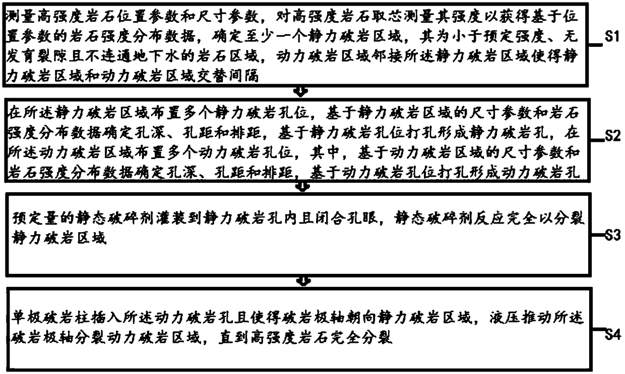
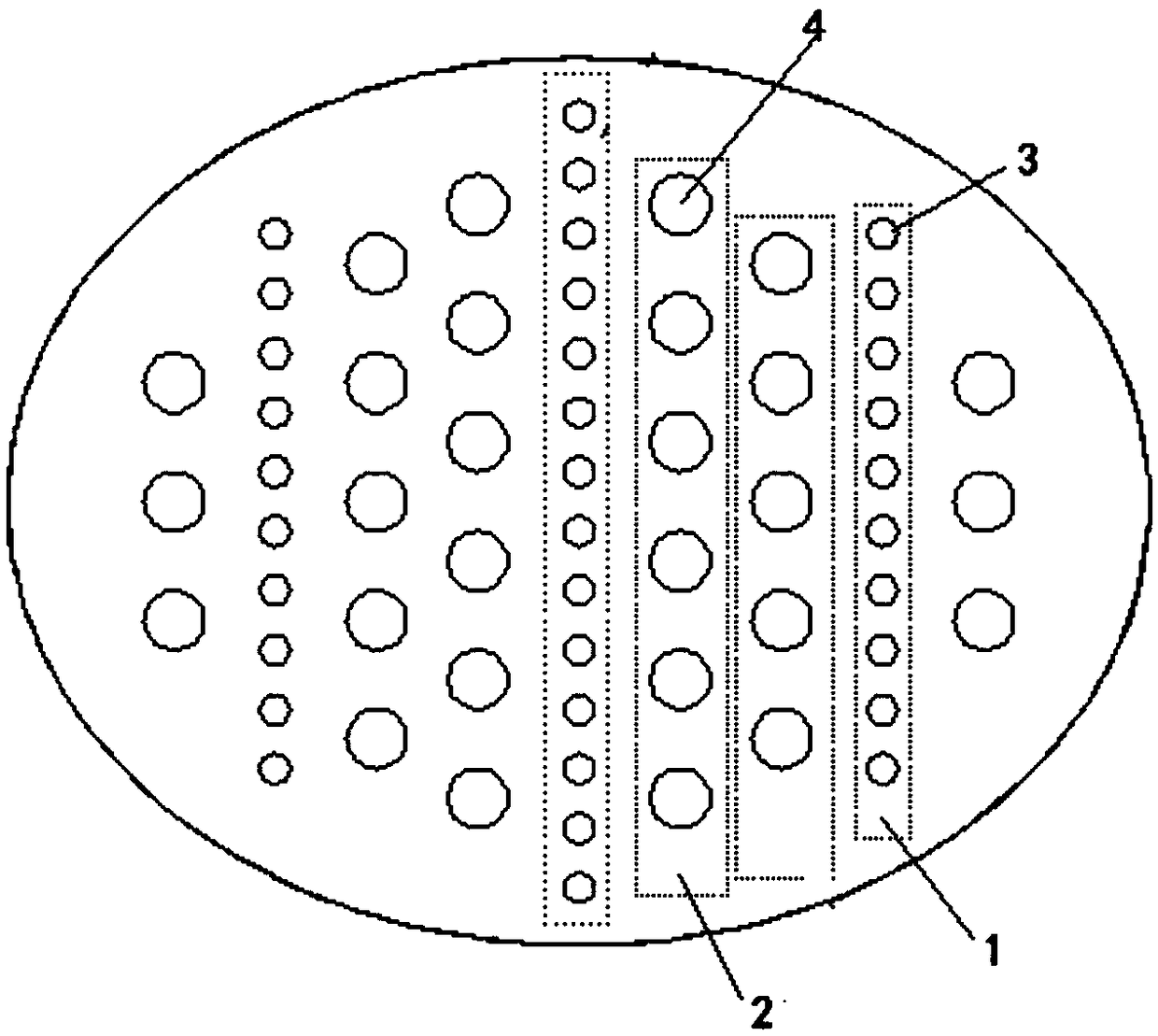
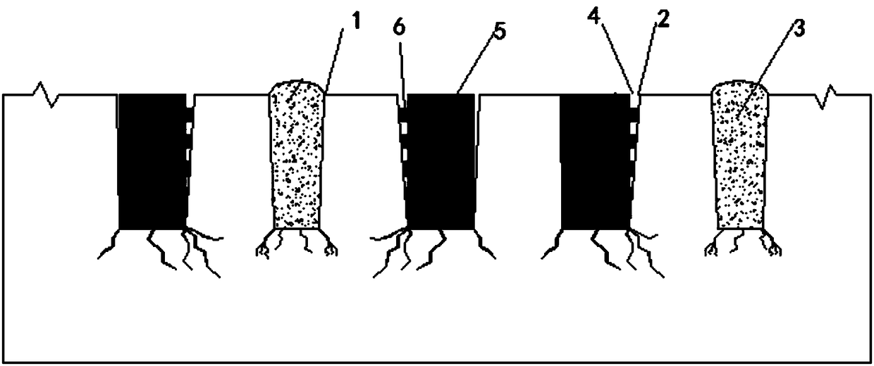
The invention discloses a high-strength rock splitting method and device based on static and dynamic alternating coupling. The method comprises the following steps: measuring the position parameter and the dimension parameter of a high-strength rock; determining at least one static force rock breaking area; enabling a dynamic force rock breaking area to be adjacent to the static force rock breaking area to cause the dynamic force rock breaking area and the static force rock breaking area to be alternate; placing a plurality of static force rock breaking hole sites in the static force rock breaking area; on the basis of the static force rock breaking hole sites, punching to form static force rock breaking holes; placing a plurality of dynamic force rock breaking hole sites in the dynamic force rock breaking area; on the basis of the dynamic force rock breaking hole sites, punching to form dynamic rock breaking holes; filling the static force rock breaking holes to close the holes with apreset quantity of static disintegrating agent; enabling the static disintegrating agent to fully react to split the static force rock breaking area; inserting a single-pole rock breaking column intothe dynamic force rock breaking hole to enable a rock breaking pole axis to face the static force rock breaking area; pushing the rock breaking pole axis by hydraulic pressure to split the dynamic force rock breaking area until high-strength rock is completely split.

Description

technical field [0001] The invention relates to the technical field of rock non-explosive fracturing, in particular to a high-strength rock splitting method and a splitting device based on static-dynamic alternating coupling. Background technique [0002] At present, blasting is still the most economical and quickest way to break rocks. However, during the blasting process, harmful effects such as blasting vibration, blasting flying stones, and toxic gases may occur. equipment is affected. In recent years, with the strengthening of people's awareness of self-protection and environmental protection, people pay more and more attention to the hazards of blasting, especially when the blasting area is very close to buildings (structures). For disputes caused by blasting, some construction units do not use conventional blasting methods, but tend to apply non-blasting excavation rock breaking technology. These requirements have also prompted people to conduct in-depth research on...

Claims


Application Information

Patent Timeline
Patent Type & Authority Applications(China)
IPC IPC(8): E21C37/08
CPCE21C37/08
Inventor 牛自强王力功候晓军燕添羽谢玮珺陶祥令苏运河程军飞李燕隆王昱鑫王刚冯新涛郭严涛路克明万雄雄
Owner CHINA RAILWAY 12TH BUREAU GRP
Learn More