
Thrombus removal device

A thrombus and thrombus head technology, applied in the field of medical devices, can solve the problems of inability to accurately judge the operation process, complicated operation of the active part, and the lumen affecting the thrombectomy efficiency, so as to improve the thrombus removal rate, the device operation is simple, and the accuracy is improved. degree of effect

Pending Publication Date: 2019-02-12
SHANGHAI BLUEVASCULAR MEDTECH CO LTD
View PDF2 Cites 4 Cited by
  • Summary
  • Abstract
  • Description
  • Claims
  • Application Information

AI Technical Summary

Problems solved by technology

[0010] One of the objectives of the present invention is to solve the problem in the prior art that large thrombi block the lumen and affect the efficiency of thrombus removal
[0011] Another purpose of the present invention is to solve the problem that doctors cannot accurately judge the operation process during electric suction, which is conducive to improving the accuracy of the operation
[0012] Another object of the present invention is to solve the problem of complex operation of the active part of the device

Method used


Image

  • Thrombus removal device
  • Thrombus removal device
  • Thrombus removal device

Examples


Embodiment 1

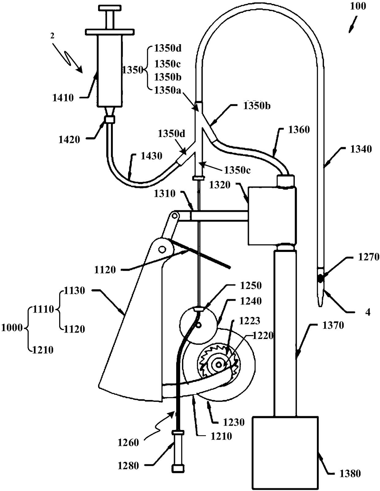
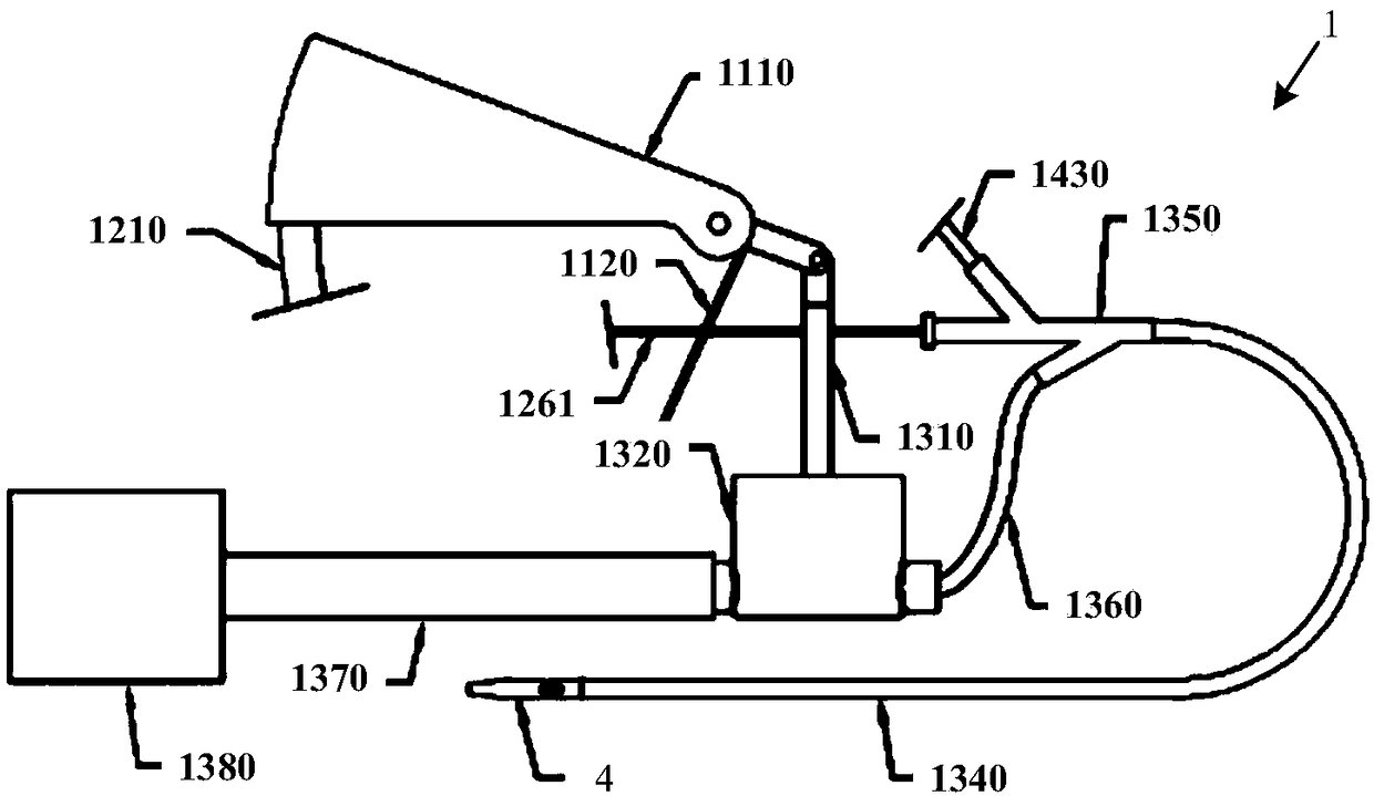
[0045] Please refer to figure 1 , which is a schematic structural view of the mechanical thrombus removal device in this embodiment, as figure 1 As shown, the mechanical thrombus removal device 100 includes a thrombus removal head 4 , a thrombus breaking system 3 and a thrombus suction system 1 , and the thrombus removal head 4 is connected to a sheath tube 1340 .

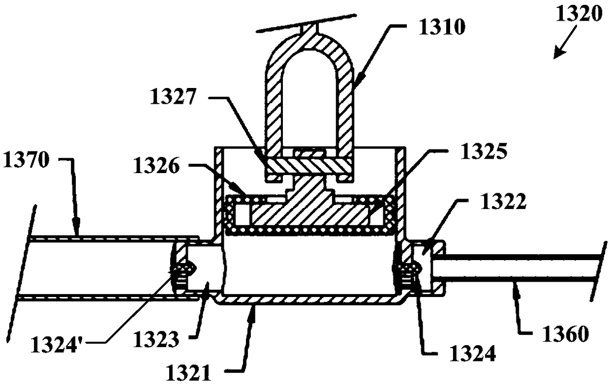
[0046] key reference Figure 4 As shown, it is a schematic structural diagram of the bolt breaking system 3 in this embodiment. Such as Figure 4 As shown, the bolt breaking system 3 includes an operating assembly 1000, a gear assembly 1200, a transmission tube 1260, and a bolt breaking knife 1270. The operating assembly drives the transmission tube 1260 to rotate through the gear assembly 1200, and the distal end of the transmission tube 1260 is connected to Broken Bolt Knife 1270. Wherein, the operation assembly 1000 includes, for example, a pressing handle 1110 and a transmission part 1210 , and the transmis...

Embodiment 2

[0074] Such as Figure 7 As shown, the difference between this embodiment and the first embodiment is that the operation assembly 1000 includes a rocker 1140 and a gear plate 1231 . Wherein, the rocker 1140 is located on one side of the gear plate 1231 and is connected by a shaft, the gear plate 1231 meshes with the third gear 1241, the third gear 1241 is coaxial with the first bevel gear 1240, and the first bevel gear 1240 and the second bevel gear 1250 engaged.

[0075] When preparing the various parts of the mechanical thrombus removal device in this embodiment, each part can be made by machining, injection molding, extrusion, laser engraving and other processing methods. The fixed connections between different components can be made by laser welding or glue bonding. For example, the front transmission tube 1263 , the middle transmission tube 1262 and the rear transmission tube 1261 are sequentially welded by laser to form the transmission tube 1260 . Specific as Figure...


PUM


Abstract

The invention provides a thrombus removal device, a thrombus absorbing system and a thrombus smashing system can be driven simultaneously by a manual operation assembly, a large thrombus is cut into small thrombi through the thrombus smashing system before the thrombus is pumped, the defect that the thrombus taking efficiency is affected due to the fact that the large thrombus blocks the lumen inthe prior art is avoided, and the operation success rate is improved. On the other side, the pumping pressure in the blood vessel can be sensed directly through the manual operation assembly, pumpingof the thrombi, the cleaning process of the thrombi and the abnormal condition can be sensed visually according to the pumping pressure change, the defect that the operation process cannot be judged accurately by the doctor during electric pumping in the prior can be avoided, and the operation accuracy is improved.

Description

technical field [0001] The invention relates to the technical field of medical devices, in particular to a mechanical thrombus removal device. Background technique [0002] Deep venous thrombosis (DVT) of the lower extremities refers to the abnormal coagulation of blood in the deep veins of the lower extremities, which belongs to the disorder of venous return of the lower extremities. There are two main complications of DVT: if the thrombosis is not treated in time at the early stage, post thrombosis syndrome (PTS) may form, which is manifested as lower extremity edema, muscle pain, pigmentation, and changes in subcutaneous tissue fibers. Local ulcers; thrombus falls off and reaches the pulmonary artery with the impact of blood, which can cause pulmonary embolism (pulmonary embolism, PE). The diagnosis rate of PE is low, and the misdiagnosis rate and mortality rate are high. [0003] DVT can be treated with anticoagulant drugs such as oral aspirin and warfarin in the early ...

Claims


Application Information

Patent Timeline
Patent Type & Authority Applications(China)
IPC IPC(8): A61B17/22A61B17/3207
CPCA61B17/22A61B17/320758A61B2017/22084A61B2017/22079A61B2017/22038A61B2017/320775A61B17/3207A61B2217/005
Inventor 韩建超张琳琳樊亚明丁双喜史增佐李中华苗铮华
Owner SHANGHAI BLUEVASCULAR MEDTECH CO LTD
Learn More