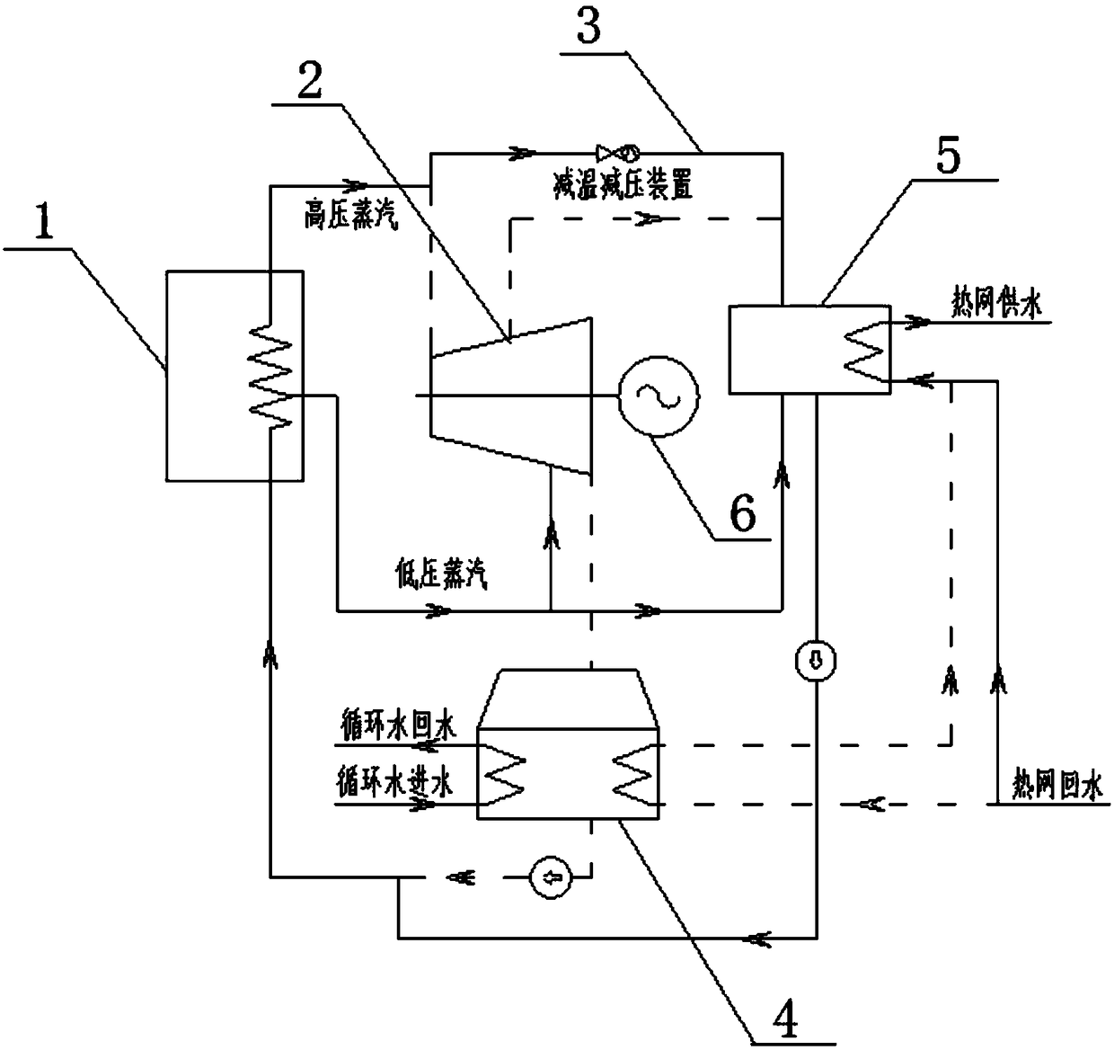
Gas and steam combined cycle high back pressure heat supply unit and method capable of realizing not stopping of gas and steam combined cycle high back pressure heat supply unit in rotor replacement

A combined cycle unit, gas steam technology, applied in heating fuel, steam engine installation, combined combustion mitigation, etc., can solve the problems of occupying unit running time, long time for rotor replacement, power generation loss, etc., to increase power generation and heat supply. The effect of increasing the power plant revenue and reducing the impact

Active Publication Date: 2019-02-12
SHANDONG HUADIAN ENERGY SAVING TECH
View PDF8 Cites 9 Cited by
  • Summary
  • Abstract
  • Description
  • Claims
  • Application Information

AI Technical Summary

Problems solved by technology

However, this technology also has disadvantages: Since the unit needs to go through the transition from the heating period to the non-heating period and from the non-heating period to the heating period every year, it needs to be shut down twice a year to replace the rotor. The rotor takes a long time, takes up the running

Method used


Image

  • Gas and steam combined cycle high back pressure heat supply unit and method capable of realizing not stopping of gas and steam combined cycle high back pressure heat supply unit in rotor replacement

Examples


Embodiment Construction

[0029] The present disclosure will be further described below in conjunction with the accompanying drawings and specific embodiments.

[0030] It should be pointed out that the following detailed description is exemplary and intended to provide further explanation to the present application. Unless defined otherwise, all technical and scientific terms used herein have the same meaning as commonly understood by one of ordinary skill in the art to which this application belongs.

[0031] It should be noted that the terminology used here is only for describing specific implementations, and is not intended to limit the exemplary implementations according to the present application. As used herein, unless the context clearly dictates otherwise, the singular is intended to include the plural, and it should also be understood that when the terms "comprising" and / or "comprising" are used in this specification, they mean There are features, steps, operations, means, components and / or ...


PUM


Abstract

The invention provides a gas and steam combined cycle high back pressure heat supply unit and a method capable of realizing not stopping of the gas and steam combined cycle high back pressure heat supply unit in rotor replacement. The gas and steam combined cycle high back pressure heat supply unit comprises a waste heat boiler, a steam turbine, a condenser and a heater for a heating network, wherein the waste heat boiler is configured to be heated through steam exhaust of the gas turbine to generate high-pressure steam and low-pressure steam; the steam turbine works rotationally through the high-pressure steam, and high back pressure steam exhaust is performed for heating heating network circulating water; the steam turbine is provided with a high pressure bypass; the high pressure bypassis used for reducing the temperature and the pressure of high-temperature steam when the steam turbine is stopped and then feeding the high-temperature steam into the heater for the heating network;and the condenser is configured to heat heating network return water through steam exhaust of the steam turbine. During the period of replacement of a steam turbine rotor, only the steam turbine is stopped, the normal operation of the gas turbine, the waste heat boiler and the like is ensured, and the high-pressure steam generated by the waste heat boiler is temperature-reduced and pressure-reduced through the high pressure bypass and then is fully used for supplying heat, so that the gas and steam combined cycle unit is not stopped, the cogeneration purpose is achieved, and the power plant efficiency is improved.

Description

technical field [0001] The disclosure relates to a gas-steam combined cycle high back pressure heating unit and a method for changing rotors without stopping combustion. Background technique [0002] Cogeneration of heat and power is one of the important ways to speed up the pace of energy saving of gas-steam combined cycle units, among which the energy saving effect of high back pressure heating transformation is the most significant. The central heating method of cogeneration can not only solve the heating problem in large and medium-sized cities, but also greatly improve the thermal efficiency of the unit. [0003] In order to realize the high back pressure heating of the unit, the gas-steam combined cycle unit adopts a specially designed heating rotor for the heating period, and switches back to the original rotor after the heating is over. The use of dual-rotor heating steam turbines can reduce the loss of cold sources during the heating period and improve the economic...

Claims


Application Information

Patent Timeline
IPC IPC(8): F01K17/02F02C6/18F01D21/00F24D3/10
CPCF01D21/00F01K17/025F02C6/18F24D3/10F24D2200/13Y02E20/14
Inventor 王爱民何洪滨岳建楠刘建华刘凤生赵艳刘文超
Owner SHANDONG HUADIAN ENERGY SAVING TECH
Why Eureka
Try Eureka