
Deviation surge absorbing structure built in contact switch

A surge absorbing and switching technology, which is applied in the field of offset surge absorbing structure, can solve the problems of flashover, the total height cannot be lowered between electrodes, and the high voltage cannot be completely insulated and covered, so as to reduce the height and improve the total height. Reduced effect

Inactive Publication Date: 2019-02-12
王怡翔 +1
View PDF10 Cites 0 Cited by
  • Summary
  • Abstract
  • Description
  • Claims
  • Application Information

AI Technical Summary

Problems solved by technology

[0014] The main technical problem to be solved by the present invention is to overcome the above-mentioned defects in the prior art, and provide an offset type surge absorbing structure built in the contact switch, which not only has the original function of the current overload protection switch In addition to functions, it uses the existing contacts of the switch, and the built-in multi-piece varistors are in a staggered and stacked offset form, so that each varistor has a vertical surface that can be connected to power supply, so as to reduce the built-in surge The height of the absorbing structure is used to improve the problems in the previous case that the total height of the surge absorbing structure cannot be reduced after the action and the electrodes cannot be completely insulated and covered, resulting in high-voltage flashover.

Method used


Image

  • Deviation surge absorbing structure built in contact switch
  • Deviation surge absorbing structure built in contact switch
  • Deviation surge absorbing structure built in contact switch

Examples


Embodiment Construction

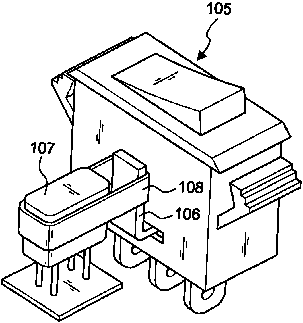
[0111] First, please refer to Figure 3~ Figure 11 As shown, a preferred embodiment of the present invention includes: a contact switch 30. The contact switch 30 disclosed below in the present invention is described with the contact switch module previously disclosed by the inventor, but not It is limited to the following structures, and any switch module with a contact function can be implemented. It includes: a shell 31, a pressing block 32 is arranged at the upper end, and a first lug 40 used as the input of the phase line (L) pole, and a second lug 40 used as the output of the phase line (L) pole are arranged at the bottom end. Wiring piece 50, and a 3rd wiring piece 60 as neutral wire (N) pole input, wherein this first wiring piece 40 is connected with a double metal sheet 41, is provided with a contact reed 42 and in the middle of this double pair metal sheet 41 A first contact point 421, the lower portion 51 of the second lug 50, relative to the position of the first c...


PUM


Abstract

A deviation surge absorbing structure built in a contact switch comprises more than two insulating positioners with deviation positioning frame surfaces and at least one insulating elastic ring. Threepiezoresistor bare chips with double weldable surfaces form an upper separation insulating area, a lower separation insulating area, a left separation insulating area and a right separation insulating area, high-voltage flashover situations are avoided by complete coating, elastic buffer protection is achieved, and vertically exposed welding area surfaces and fastening area surfaces with independent partitions are formed due to deviation and can be used for connecting welding parts with fastening parts. More than three piezoresistors are overlapped in a staggered and deviating manner, long-distance welding and fastening area surfaces with the same phase line polarity are formed on opposite side, two ends of one metal fastening part can be welded and positioned by low-temperature tin alloyconnectors, a compressed elastic actuator can flick a push portion when the low-temperature tin alloy connectors are separated by hot melting, and contact joints in the contact switch are pushed open, so that the switch is turned off. Therefore, components can be simplified, insulation is true, and the height of the built-in surge absorbing structure is greatly reduced.

Description

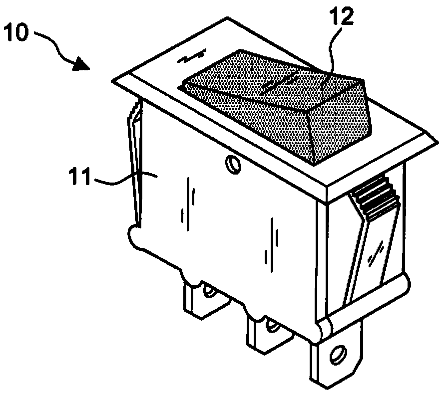
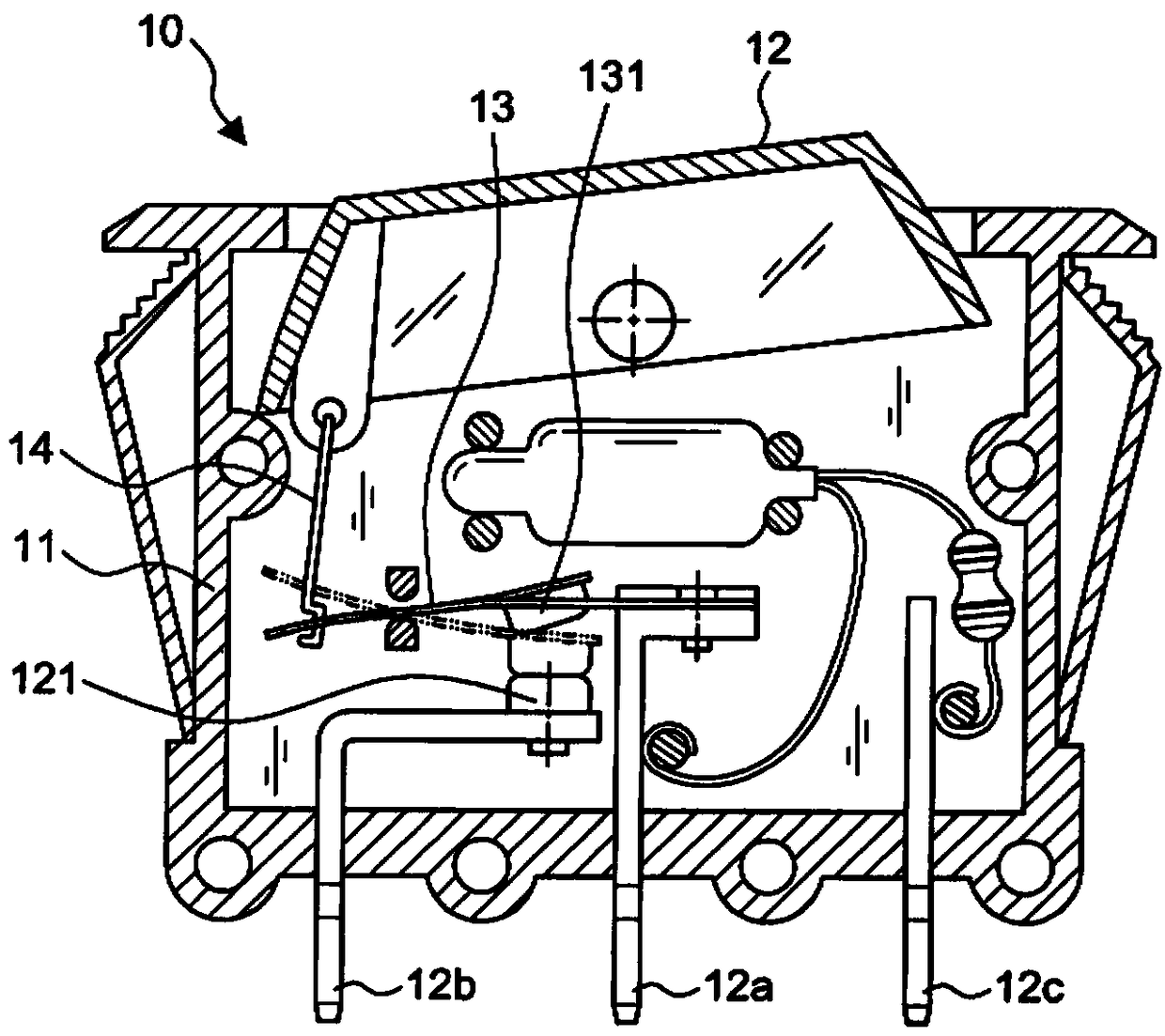
technical field [0001] The invention relates to an offset type surge absorbing structure built in a contact switch, in particular to an offset type in which multiple built-in varistors are staggered and stacked, so that each varistor The vertical surface with power connection can reduce the height of the built-in surge absorbing structure. Background technique [0002] Figure 1A and Figure 1B It discloses an existing overcurrent protection switch 10, which generally includes: a casing 11, a pressure block 12 is provided at the upper end, and a first lug 12a, a second lug 12b and a third lug are arranged at the bottom. Lug 12c, wherein the first lug 12a is provided with a double metal contact reed 13 and a first contact 131, and the second lug 12b is provided with a second contact 121 that can be in contact with the first contact. ; a linkage 14, one end of which pivot is located at the bottom of the briquetting block 12, and the other end links the free end of the double...

Claims


Application Information

Patent Timeline
IPC IPC(8): H01H71/20
CPCH01H71/20
Inventor 王怡翔王怡颖
Owner 王怡翔
Learn More