
Cascade energy storage system and method for improving power quality of power grid

A technology for power quality and energy storage systems, applied in AC network load balancing, AC network to reduce harmonics/ripples, harmonic reduction devices, etc. It can solve the problem that the harmonic voltage compensation function of series converters is difficult to integrate and distribute in parallel. In order to avoid unstable operation, reduce equipment cost and input cost, and improve flexibility and reliability

Active Publication Date: 2019-02-12
STATE GRID SHANDONG ELECTRIC POWER +4
View PDF4 Cites 6 Cited by
  • Summary
  • Abstract
  • Description
  • Claims
  • Application Information

AI Technical Summary

Problems solved by technology

Using unified power flow controller (UPQC) to compensate harmonic voltage and harmonic current at the same time is undoubtedly an effective solution, but UPQC uses parallel converters to improve current quality, and series converters to improve voltage quality, and phase-to-phase interference can easily lead to unstable operation. The extraction of harmonic voltage and current is too heavy for the calculation burden of the controller, and the harmonic voltage compensation function of the series converter is difficult to integrate into the parallel distributed energy converter, resulting in excessive investment in equipment costs

Method used


Image

  • Cascade energy storage system and method for improving power quality of power grid
  • Cascade energy storage system and method for improving power quality of power grid
  • Cascade energy storage system and method for improving power quality of power grid

Examples


Embodiment Construction

[0043] It should be pointed out that the following detailed description is exemplary and intended to provide further explanation to the present application. Unless defined otherwise, all technical and scientific terms used herein have the same meaning as commonly understood by one of ordinary skill in the art to which this application belongs.

[0044] It should be noted that the terminology used here is only for describing specific implementations, and is not intended to limit the exemplary implementations according to the present application. As used herein, unless the context clearly dictates otherwise, the singular is intended to include the plural, and it should also be understood that when the terms "comprising" and / or "comprising" are used in this specification, they mean There are features, steps, operations, means, components and / or combinations thereof.

[0045] In one or more embodiments, a cascaded energy storage system for improving the power quality of the power...


PUM


Abstract

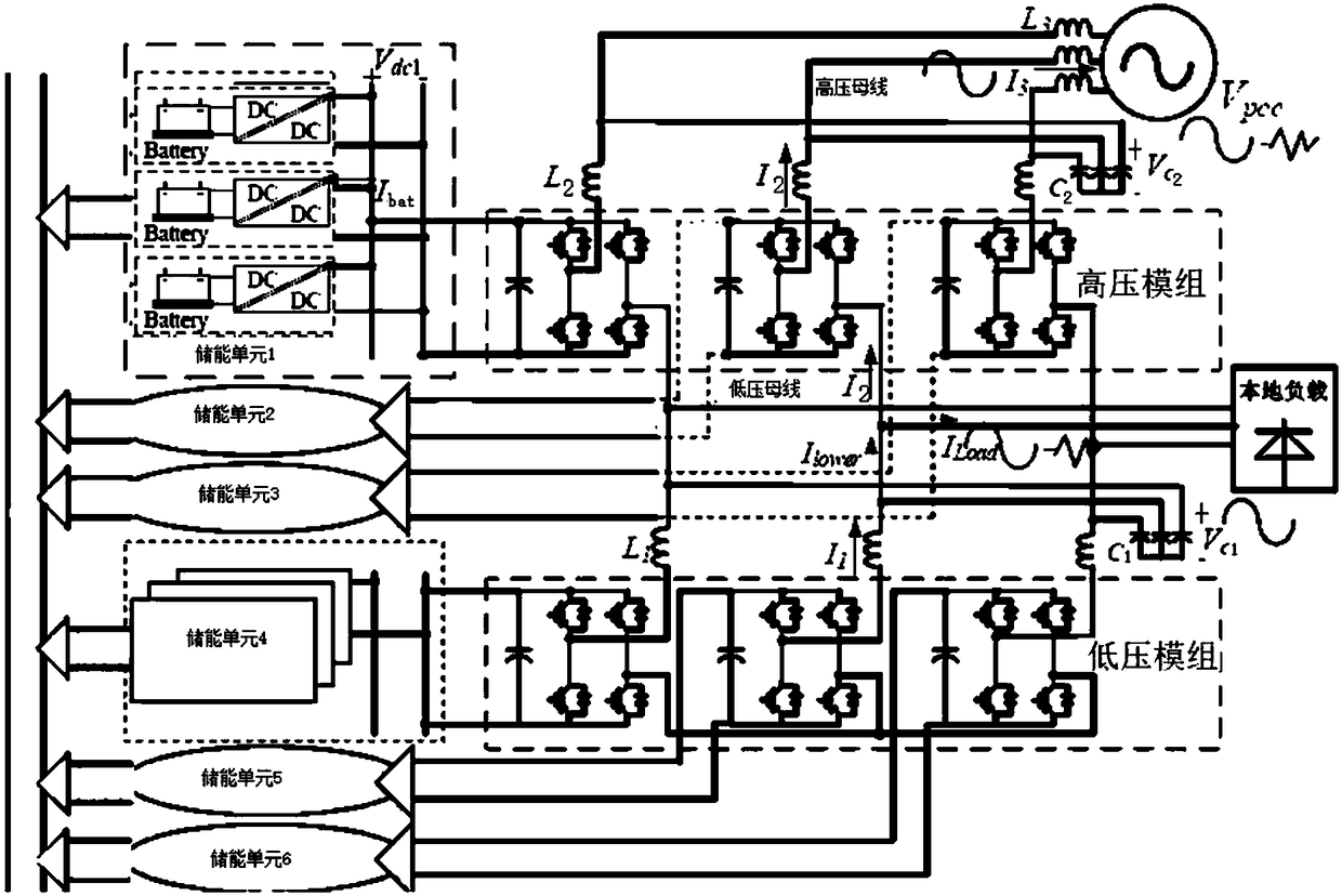
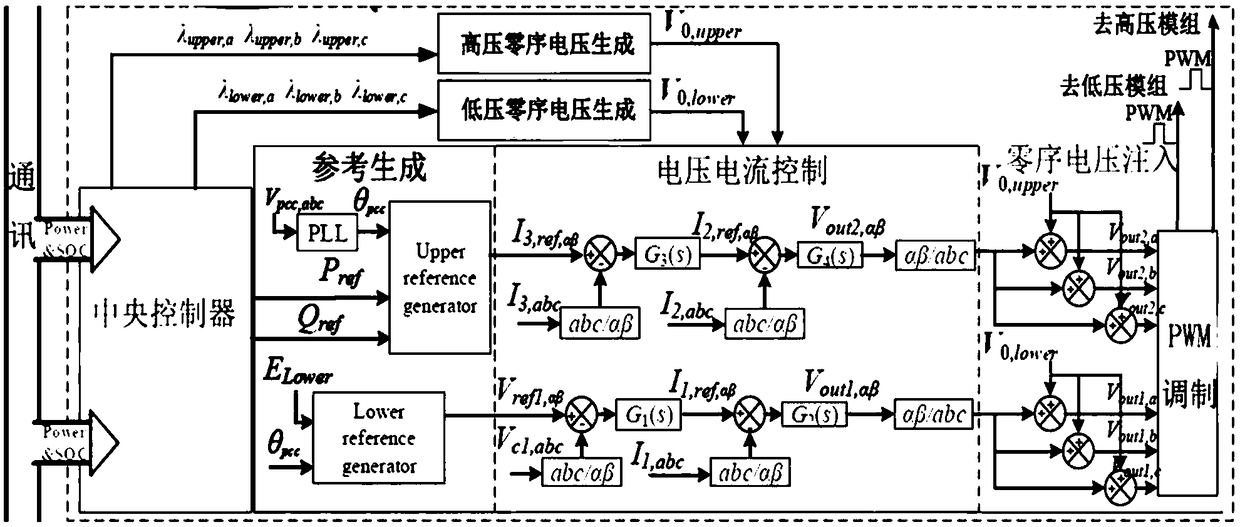
The invention discloses a cascade energy storage system and method for improving power quality of a power grid. The system comprises distributed energy storage units, a low-voltage module group and ahigh-voltage module group, wherein the low-voltage module group comprises a plurality of cascaded H-bridge circuits; the low-voltage module group is connected to a low-voltage alternating current busthrough a filter; the high-voltage module group comprises a plurality of the cascaded H-bridge circuits; the high-voltage module group is connected in parallel between a low-voltage bus and a high-voltage bus through the filter; each distributed energy storage unit is connected to the low-voltage module group or the high-voltage module group through one of the H-bridge circuits; and each distributed energy storage unit is connected to the corresponding module group through the H-bridge circuit to form a three-phase independent structure. Through the cascade H-bridge series structure, the energy storage system can be directly connected to the medium-voltage or even high-voltage power grid without isolation of a transformer, and the voltage of the direct-current side of CHB connected to theenergy storage system does not need to be very high, and thus the flexibility and reliability of the operation of the energy storage system are improved.

Description

technical field [0001] The invention relates to the technical field of energy storage, in particular to a cascaded energy storage system and a control method for improving power quality of a grid. Background technique [0002] With the high penetration of distributed energy such as new energy and energy storage into the modern power system, the use of grid-connected inverters or distributed energy converters for power quality management has attracted widespread attention due to its flexibility and low cost. In order to realize the above functions, harmonic extraction and wide bandwidth current controller are integrated into the grid-connected inverter. Distributed power multifunctional converters mainly focus on local load harmonic current compensation, similar to traditional active power filters. However, the above research mainly focuses on the improvement of grid current quality, and it is difficult to compensate grid voltage harmonics by suppressing grid current harmoni...

Claims


Application Information

Patent Timeline
Patent Type & Authority Applications(China)
IPC IPC(8): H02J3/32H02J3/01
CPCH02J3/01H02J3/32Y02E40/40
Inventor 王瑞琪李荣孙旭日许玮慕世友吴绍军康文明贾亚军李勇李笋李文升王超安树怀吕伟龙梁健
Owner STATE GRID SHANDONG ELECTRIC POWER
Learn More