
Pellet production apparatus and pellet production method

A particle manufacturing and spraying device technology, which is applied in the field of thermoplastic resin particle manufacturing devices, can solve problems such as yield reduction, achieve the effect of improving quality and suppressing the generation of continuous particles

Active Publication Date: 2019-02-12
DIC CORPORATION
View PDF3 Cites 2 Cited by
  • Summary
  • Abstract
  • Description
  • Claims
  • Application Information

AI Technical Summary

Problems solved by technology

However, in this method, since the strands discharged from the outlet of the feeder are excessively cooled, the strands become hard and brittle, so there are problems such as frequent cutting before being introduced into the cutting machine, which reduces the yield.

Method used


Image

  • Pellet production apparatus and pellet production method
  • Pellet production apparatus and pellet production method
  • Pellet production apparatus and pellet production method

Examples


Embodiment

[0081] Hereinafter, the present invention will be described in more detail based on examples, but the present invention is not limited thereto.

[0082] (Pellet manufacturing device)

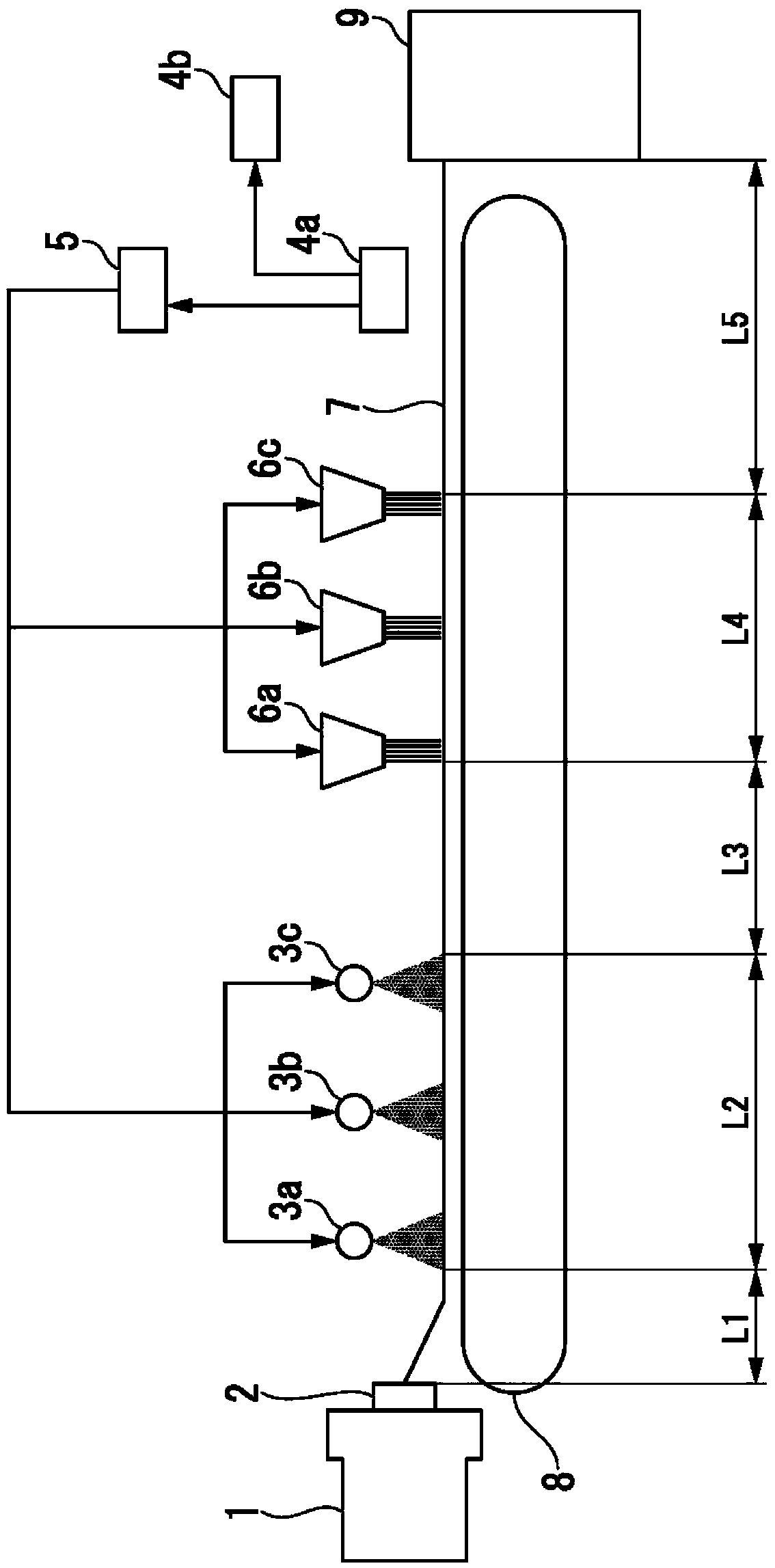
[0083] use figure 1 The manufacturing apparatus used in the examples of the present invention will be described. First, a discharge port 2 was attached to the front end of a feeder 1 for melting a thermoplastic resin (twin-screw extruder "TEM-26" manufactured by Toshiba Machine Co., Ltd.) so as to discharge 15 strands. Then, set the conveyor belt 8 for conveying the discharged strands (the contact surface with the strands is a herringbone twill stainless steel mesh), on the top of the conveyor belt conveying surface, at equal intervals along the conveying direction of the conveyor belt and at a height of 170 mm from the conveyor belt Configure three liquid spray devices 3a to 3c for cooling the strands conveyed by the conveyor belt, and then arrange three gas blowing devices 6a to 6c at equal...

Embodiment 1

[0102] According to the ratio shown in Table 2, (A1) polyethylene terephthalate ("MA-2103" manufactured by UNITIKA Co., Ltd., melting point 255 ° C, Tg 70 ° C) and (B1) calcium carbonate (Maruo Calcium Co., Ltd. "CALTEX 5" (powder, average particle size: 1.2 μm)) was dry-mixed, and then the raw materials were supplied and melt-kneaded under the conditions shown in Table 2 using a twin-screw extruder, and then, use figure 1 The particle production apparatus shown performs the production of particles. That is, a plurality of strands (strand diameter: 3 mm) were discharged from the discharge port of the melt-kneading device. While conveying 15 strands on a conveyor belt at a rate of 50 m / min, the atmosphere temperature of the conveyor belt was kept at room temperature (23° C.) for 3 hours and continuous production was performed to produce pellets.

[0103] Such as figure 1 As shown, the measuring device 4 a is disposed between the gas blowing device 6 c and the strand cutter...


PUM

PropertyMeasurementUnit
melting pointaaaaaaaaaa
pore sizeaaaaaaaaaa
diameteraaaaaaaaaa

Abstract

The purpose of the present invention is to provide: a thermoplastic resin pellet production method that, even when production is performed continuously for long periods, limits the occurrence of connected pellets and pellet cut surface tails and defects, suppresses the generation of fines, and improves pellet quality and productivity; and a pellet production apparatus useful for said production method. The apparatus is provided with a belt conveyor for conveying strands obtained by melting a composition comprising a thermoplastic resin and an additive and then discharging same from a feeder (1), a liquid-spraying device for spraying liquid on the conveyed strands, a gas-blowing device for blowing a gas on the conveyed strands, and a strand-cutting device for cutting the conveyed strands into pellets. The liquid-spraying device, gas-blowing device and strand-cutting device are disposed in said order in the strand conveyance direction. The apparatus is provided with a measurement device,which is disposed upstream of the strand-cutting device in the conveyance direction and is for measuring the surface temperature of the strands, and an adjustment mechanism for adjusting the drivingof the liquid-spraying device and / or the gas-blowing device on the basis of the measured surface temperature.

Description

technical field [0001] The present invention relates to an apparatus for producing thermoplastic resin pellets and a method for producing the same. More specifically, it relates to cooling and cutting strands obtained by discharging a melted thermoplastic resin or a resin composition containing the thermoplastic resin through a kneader, extruder, etc. (hereinafter referred to as "supplier") The granule manufacturing device and granule manufacturing method used for granulation. Background technique [0002] Generally speaking, the manufacturing process of thermoplastic resin products includes: a process of mixing resin raw materials with additive materials such as glass fibers, flame retardants, mold release agents, and colorants, and performing kneading and granulation; The secondary process in which the granulated pellets are fed into an injection molding machine, melted, and molded into a product shape using a mold. [0003] From the point of view of effectively performi...

Claims


Application Information

Patent Timeline
Patent Type & Authority Applications(China)
IPC IPC(8): B29B9/06B29C48/355B29C48/88B29C48/885
CPCB29B9/06B29C48/355B29B7/726B29C48/0022B29C48/885B29C48/92B29C48/04B29C2948/92209B29C2948/92428B29C2948/92704B29B9/10B29C48/88B29B7/90B29K2067/003B29K2509/02
Inventor 樱井佳延熊谷泰彰池田久德中西康治入口康弘深泽一成山口裕史
Owner DIC CORPORATION
Learn More