
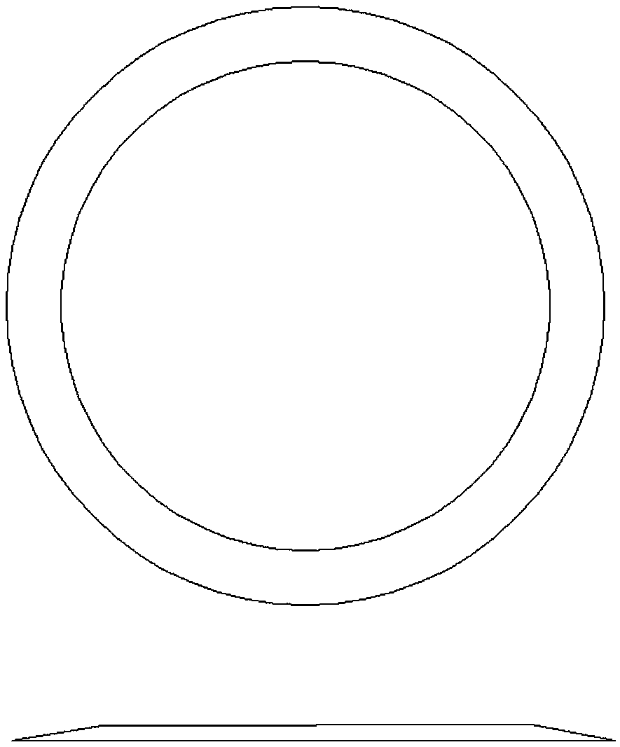
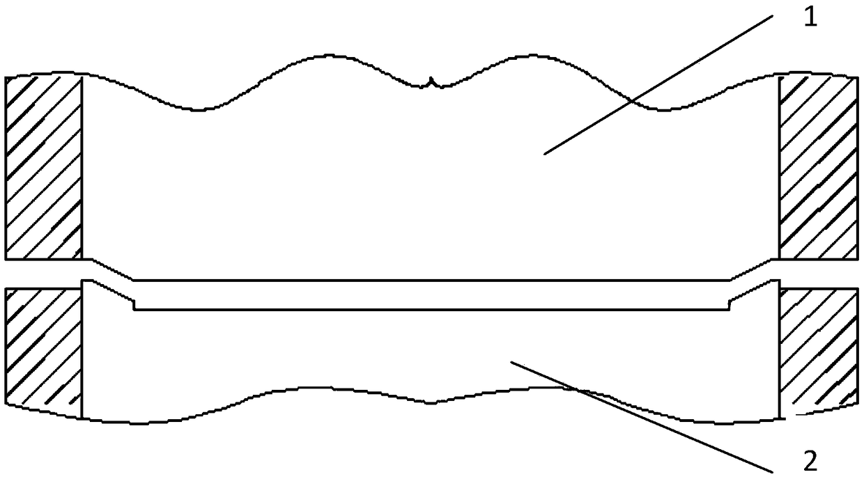
Optimized stamping forming process method of accumulator diaphragm capsule diaphragm

A stamping forming and process method technology, applied in the stamping and forming field, can solve the problems such as the height and size of the diaphragm parts being out of tolerance, and achieve the effect of reasonable distribution of the springback value and improvement of the flatness.

Active Publication Date: 2019-02-15
SHANGHAI AEROSPACE EQUIP MFG GENERAL FACTORY
View PDF10 Cites 3 Cited by
  • Summary
  • Abstract
  • Description
  • Claims
  • Application Information

AI Technical Summary

Problems solved by technology

[0005] The technical problem of the present invention is: to overcome the deficiencies of the prior art, provide an optimized stamping forming method, and solve the problem of excessive height and dimension of diaphragm parts

Method used


Image

  • Optimized stamping forming process method of accumulator diaphragm capsule diaphragm
  • Optimized stamping forming process method of accumulator diaphragm capsule diaphragm
  • Optimized stamping forming process method of accumulator diaphragm capsule diaphragm

Examples


Embodiment 1

[0038] Processing outer diameter the inside diameter of High temperature 1.5mm, thickness 0.3mm superalloy GH4169 diaphragm.

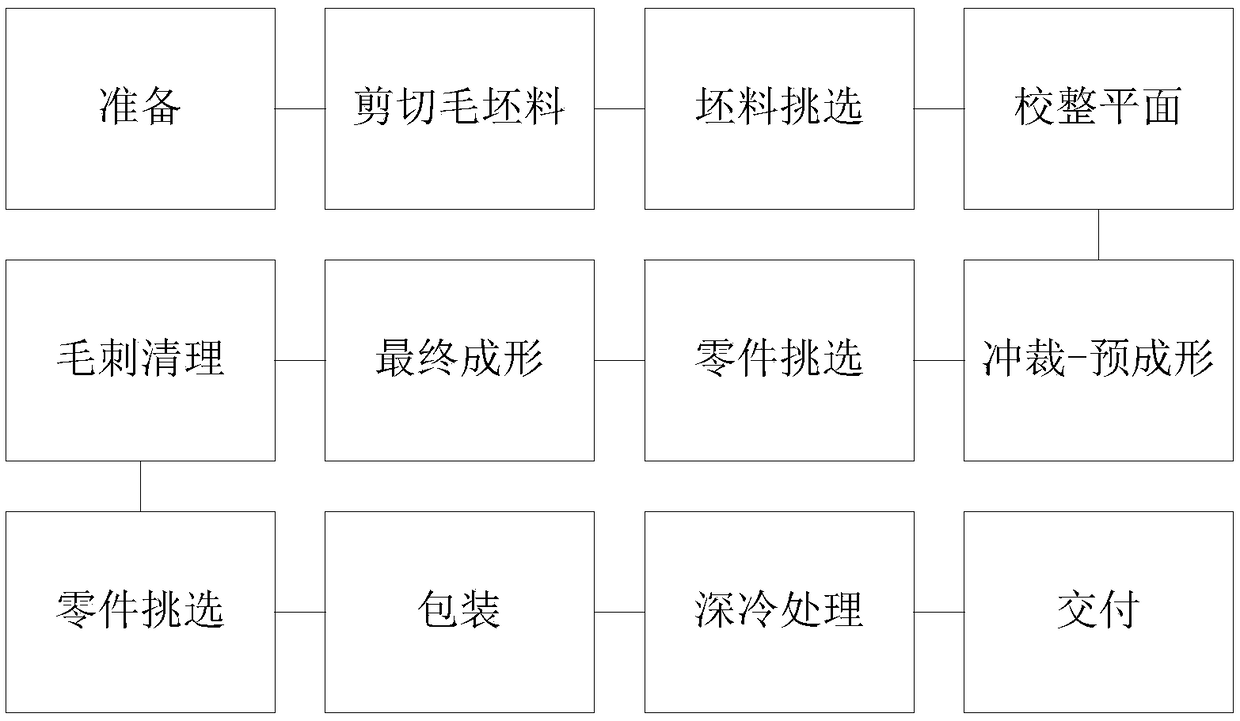
[0039] The processing flow chart is attached image 3 shown.

[0040] (1) Preparation of equipment and tooling

[0041] According to the forming requirements and actual conditions of the parts, select the appropriate stamping equipment, and it can be realized if the requirement is greater than 50T. According to the external dimension requirements of the diaphragm part, the initial forming mold design scheme is determined by using the finite element analysis tool, and the springback angle value of the mold is determined.

[0042] According to theoretical analysis and calculation results, the blanking-preforming height value is 1.2mm, and the final forming die height value is 2.0-2.1mm.

[0043] (2) Stamping blanks

[0044] Uncoil and cut 200×200mm rough blanks, check and select the surface quality of the cut rough blanks, and adjust the flatness...

Embodiment 2

[0055] Processing outer diameter the inside diameter of High temperature 1.5mm, thickness 0.2mm superalloy GH4169 diaphragm.

[0056] The processing flow chart is attached image 3 shown.

[0057] (1) Preparation of equipment and tooling

[0058] According to the forming requirements and actual conditions of the parts, select the appropriate stamping equipment, and it can be realized if the requirement is greater than 50T. According to the external dimension requirements of the diaphragm part, the initial forming mold design scheme is determined by using the finite element analysis tool, and the springback angle value of the mold is determined.

[0059] According to theoretical analysis and calculation results, the blanking-preforming height is 1.1mm, and the final forming die height is 1.8-2.0mm.

[0060] (2) Stamping blanks

[0061] Uncoil and cut 150×150mm rough blanks, check and select the surface quality of the cut rough blanks, and correct the flatness of the rou...


PUM


Abstract

The invention relates to an optimized stamping forming process method of an accumulator diaphragm capsule diaphragm. The optimized stamping forming process method of the accumulator diaphragm capsulediaphragm comprises the following steps that (1) a stamping blank is optimized to improve the flatness of the blank; (2) a stamping process is optimized, forming is achieved in two steps; and (3) a reasonable rebound value of a die is determined. Before the parts are machined, bending angles of the parts in the two stages of blanking-pre-forming and final forming are reasonably distributed. Beforeforming, a finite element analysis tool can be used for simulation calculation to obtain a distribution value; and then the die test verification of the die is carried out, the test result is evaluated, and the die size is corrected appropriately. Through a series of iterative analysis, structural parameters of the die can be finally determined, mainly the bending springback angle value is determined. Through the corrected rebound, the final size of the diaphragm parts can be ensured.

Description

technical field [0001] The invention relates to a stamping processing process of a high-temperature alloy ultra-thin strip, in particular to a stamping forming process of a diaphragm used for a bellows of a pressure accumulator of a launch vehicle, and belongs to the field of stamping forming. Background technique [0002] The new generation of launch vehicle pressure accumulator bellows is a tubular element formed by multiple ultra-thin hollow diaphragms formed by stamping and welded alternately along the inner and outer edges using precision welding technology. Compared with the traditional bellows, bellows products have smaller rigidity, better fatigue performance and higher sensitivity. With the higher requirements for components of the new generation of launch vehicles, bellows products gradually replace bellows and become Key components of the new generation of launch vehicle pressure accumulators and valves. The physical photos of capsule products are as follows: fi...

Claims


Application Information

Patent Timeline
IPC IPC(8): B21D35/00B21D53/00
CPCB21D35/002B21D53/00
Inventor 王煜胡蓝王锦浩王兵肖冰娥王建光雷湘衡
Owner SHANGHAI AEROSPACE EQUIP MFG GENERAL FACTORY
Learn More