Charging device for new energy vehicle in motion

A technology of new energy vehicles and charging devices, which is applied in the direction of electric vehicle charging technology, charging stations, electric vehicles, etc., can solve problems affecting road safety, increasing capital investment, and large volume of power receiving devices, so as to ensure the conductive effect and guarantee Charging effect, effect suitable for promotion

Inactive Publication Date: 2019-02-15
丁乃祥
View PDF1 Cites 3 Cited by
  • Summary
  • Abstract
  • Description
  • Claims
  • Application Information

AI Technical Summary

Problems solved by technology

[0002] The current electric vehicles mainly adopt the conductive charging method, which needs to use a charging cable to connect the charger and the electric vehicle, and has the following disadvantages: 1. The charging current is large, making the plug-in large and bulky, which affects the appearance; 2. When charging , need to stop first, and then connect the charging cable on the charger to the charging interface on the electric vehicle, which is cumbersome to operate; 3. Due to the mechanical friction between the socket and the socket, the reliability will deteriorate after long-term use, which will affect the charging effect; 4. When the cable is aging, in rainy and snowy weather, if you forget to unplug the socket after charging, it will easily cause leakage, which will lead to safety accidents; 5. Limited by the current battery technology, the electric vehicle itself is still expensive , heavy body, large space occupied by the battery pack, short cruising range, long charging time and frequent charging, etc.
[0004] With the country's increasing emphasis on environmental protection, reducing greenhouse gas emissions in the transportation sector is an important means to solve global gas changes. Electric vehicles have less impact on the environment than traditional vehicles. According to national conditions, pure electric vehicles should be vigorously promoted. Direction, electric vehicles will not produce exhaust gas and exhaust pollution like internal combustion engine vehicles, which is very beneficial to environmental protection. However, the existing electric vehicles are limited by the current battery technology, and the cruising range of electric vehicles has always been It is a big problem that seriously affects the promotion of electric vehicles
[0005] In order to solve the mileage problem of electric vehicles, the existing solution is to set up charging piles or charging stations along the road, but the number of vehicles charged by charging piles or charging stations within a certain period of time is limited, so more charging piles need to be set up Or charging station, which increases the capital investment, and also invents a car backup power supply or a trailer-type mobile power supply similar to a power bank to charge an electric vehicle with insufficient power, so as to realize the way of charging while driving, but this method makes the electric vehicle become heavy and cumbersome, while affecting road safety
[0006] At present, the application of existing electric vehicle charging technology mainly relies on the support of a wide range of fixed charging stations. However, charging stations cannot store a large amount of electric energy for electric vehicles in a short period of time. The result is a waste of time and inconvenience. The main obstacle to the development of electric vehicles
There is a technical solution that can wirelessly power electric vehicles while driving on the road. Although it has not yet reached maturity and practicality, the future development direction
The patent document with the publication number CN102629400A discloses an invention patent for an automatic charging device for waterproof guide rails for electric vehicles on roads. The device can automatically connect and receive electricity. It is an effective solution for road charging when wired power supply transitions to wireless power supply. Its disadvantages are: 1. The waterproof guide rail can only prevent general rainwater. electrical short circuit due to water intrusion
2. The insulating track of the waterproof guide rail is complex and costly
3. The power receiving device is large in size, which is not conducive to storing the bottom of the vehicle
4. The two-way waterproof guide rail charging road is not suitable for urban roads with many intersections

Method used


Image

  • Charging device for new energy vehicle in motion
  • Charging device for new energy vehicle in motion
  • Charging device for new energy vehicle in motion

Examples


Embodiment 1

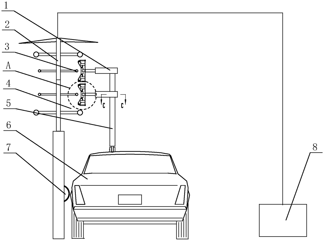
[0041] Such as Figure 1-Figure 7 As shown, the charging device for new energy vehicles in the present invention includes a fixed part and a moving part,

[0042] The fixed part includes a railing 2, a fixed rod is vertically arranged on the railing 2, and a metal contact wire 3 is arranged on the fixed rod, and the contact wire 3 is connected to the power supply system 8;

[0043] The moving part includes a folding rod 5, which is arranged on the top of the car 6, and the end of the folding rod 5 is fixed with an adapter, which is connected with the charging system of the car 6.

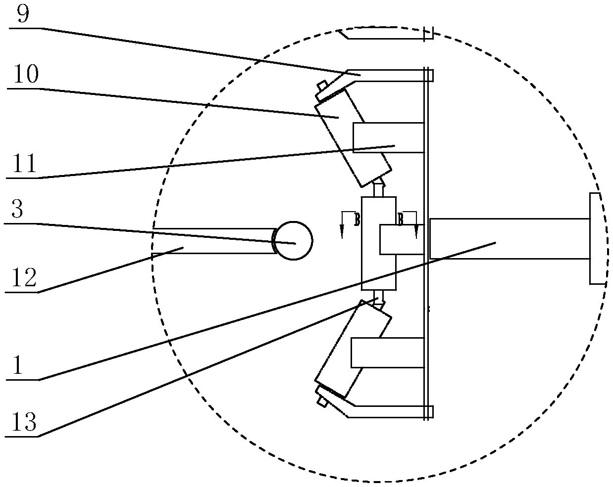
[0044]The contact wire 3 is propped up by a plurality of support rods 12 , and then the two ends of the contact wire 3 are tightened by tension wires 16 , and both the support rods 12 and the tension wire 16 are fixed on the railing 2 .

[0045] The end of the support rod 12 is in a concave arc shape, so that it fits with the contact wire 3 to prevent the contact wire 3 from shifting.

[0046] The...

Embodiment 2

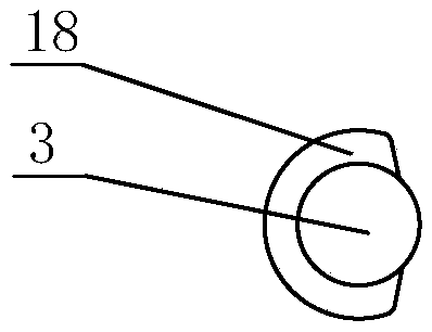
[0063] Such as Figure 8 As shown, the lapper uses concave rollers, which can achieve the same technical effect as that of Embodiment 1.


PUM


Abstract

The invention relates to a charging device for a new energy vehicle in motion, and belongs to the field of automobiles. The charging device comprises a fixed part and a moving part, and the fixed partcomprises a railing. A fixing rod is vertically arranged on the railing, a metal contact line is arranged on the fixing rod, and the contact line is connected with a power supply system. The moving part comprises a folding rod, and the folding rod is arranged at the top of the vehicle. An lap joint machine is fixed to the end part of the folding rod, and the lap joint machine is connected with acharging system of the vehicle. Charging can be performed during driving, and charging is stable; and the structure is simple, the cost is low, and the charging device is quite suitable for popularization.

Description

technical field [0001] The invention relates to a charging device for a running new energy vehicle, which belongs to the field of automobiles. Background technique [0002] The current electric vehicles mainly adopt the conductive charging method, which needs to use a charging cable to connect the charger and the electric vehicle, and has the following disadvantages: 1. The charging current is large, making the plug-in large and bulky, which affects the appearance; 2. When charging , need to stop first, and then connect the charging cable on the charger to the charging interface on the electric vehicle, which is cumbersome to operate; 3. Due to the mechanical friction between the socket and the socket, the reliability will deteriorate after long-term use, which will affect the charging effect; 4. When the cable is aging, in rainy and snowy weather, if you forget to unplug the socket after charging, it will easily cause leakage, which will lead to safety accidents; 5. Limited...

Claims


Application Information

Patent Timeline
Patent Type & Authority Applications(China)
IPC IPC(8): B60L5/00B60M1/12B60L53/14
CPCB60L5/00B60M1/12Y02T10/70Y02T10/7072Y02T90/14
Inventor 丁乃祥
Owner 丁乃祥
Why Eureka
Try Eureka