

Autonomous positioning navigation method for mobile detection robot
A technology of autonomous positioning and navigation methods, applied in the direction of navigation computing tools, etc., can solve problems that affect the accuracy of robot positioning and are susceptible to noise
- Summary
- Abstract
- Description
- Claims
- Application Information
AI Technical Summary
Problems solved by technology
Method used
Image

Examples
specific Embodiment approach 1
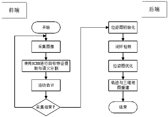
[0025] A method for autonomous positioning and navigation of a mobile detection robot in this embodiment, such as figure 1 As shown, the method is realized through the following steps:
[0026] Step 1. The sensor reads the image information, and then preprocesses the image information, and the preprocessed information is transmitted to the V-SLAM system; among them, the visual SLAM system (visual SLAM) refers to the image as the main source of environmental perception information The real-time positioning and map construction system of V-SLAM can be applied to unmanned driving, augmented reality and other application fields, and is a popular research direction in recent years; V-SLAM system refers to SLAM based on visual sensors; A series of continuously changing images for localization and map construction;
[0027] Step 2. The estimation process of the visual odometer, also called the perception front end:
[0028] Estimate the pose information of the camera motion and bui...
specific Embodiment approach 2
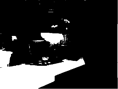
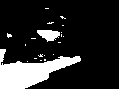
[0037] Different from Embodiment 1, in this embodiment, a method for autonomous positioning and navigation of a mobile detection robot, the estimation process of the visual odometry described in Step 2 is specifically: the core problem to be solved is the camera between adjacent images exercise, such as Figure 2a-Figure 2b shown, apparently Figure 2a Rotate left to get Figure 2b , which is a direct reflection of the human eye. If it is a camera, it can be seen from the picture, Figure 2b The central part on the left side of the image appears more in the right image, that is, the cabinets in the distance appear more in the image; while Figure 2b A part of the cabinet at the corresponding position disappears from the picture. Based on the above information, the movement trend of the camera can be judged perceptually: when the camera captures Figure 2b After the position is rotated to the left, you can shoot Figure 2b .
[0038] But this is only the perceptual percep...
specific Embodiment approach 3
[0039] Different from the first or second specific embodiment, in this embodiment, a method for autonomous positioning and navigation of a mobile detection robot, the back-end optimization process described in step three is specifically: in a general sense, the main task of the back-end is to optimize Noisy data during SLAM process. Physically speaking, as long as there is measurement, there will be errors, so the data obtained by even the most accurate sensors will also have errors, and some low-cost sensors will have larger errors. The main problem of back-end optimization is to estimate the overall state of the system from the noisy sensor data: including the trajectory of the robot itself, the map of the surrounding environment, and how uncertain the results obtained from the above state estimation are. called the maximum a posteriori probability estimate;
[0040] Visual odometry is also called the front end of visual SLAM. The main task is to provide noisy data to the b...
PUM
 Abstract
Description
Claims
Application Information