
A method for evaluating the structural state of a transmission tower

A technology for structural status and transmission towers, applied in the direction of electrical digital data processing, special data processing applications, instruments, etc., can solve problems such as loose bolts, affecting the operation safety of transmission towers, complex line routing areas, etc., to facilitate structural problems and evaluation Scientific and rigorous process, good technical effect and application effect

Pending Publication Date: 2019-02-15
ELECTRIC POWER RESEARCH INSTITUTE OF STATE GRID SHANDONG ELECTRIC POWER COMPANY +2
View PDF3 Cites 7 Cited by
  • Summary
  • Abstract
  • Description
  • Claims
  • Application Information

AI Technical Summary

Problems solved by technology

Another type of accident is the change of inherent characteristics caused by material aging, bolt looseness, corrosion and other performance degradation of the tower structure after long-term service. Even if the design standard for disaster climate conditions is not exceeded, it may cause local damage to the structure and gradually evolve into instability or fracture. down tower
Another category is the complex area of ​​the line route. For example, the transmission tower is located in the goaf of the coal mine, the heavy industrial pollution area, the river, lake and wetland area, and the mountainous area prone to landslides. Changes in the surrounding environment will affect the operation safety of the transmission tower.
[0004] The current judgment on the operation status of transmission towers is generally based on visual inspection, such as regular inspections, inspection of loose bolts, missing or deformed rods, corrosion of tower materials, changes in the root of the tower, and foundation settlement, etc., and then judge the transmission tower based on experience Whether it is reliable to operate, lack of theoretical support

Method used


Image

  • A method for evaluating the structural state of a transmission tower
  • A method for evaluating the structural state of a transmission tower
  • A method for evaluating the structural state of a transmission tower

Examples


Embodiment Construction

[0036] The specific embodiments of the present invention will be described in detail below in conjunction with the accompanying drawings. The following disclosure provides specific embodiments for realizing the devices and methods of the present invention, so that those skilled in the art can more clearly understand how to realize the present invention. To simplify the disclosure of the present invention, components and arrangements of specific examples are described below. Furthermore, the present invention may repeat reference numerals or letters in different examples. This repetition is for simplicity and clarity and does not in itself indicate a relationship between the various embodiments or arrangements discussed. It should be noted that components illustrated in the figures are not necessarily drawn to scale. Descriptions of well-known components and processing techniques and processes are omitted herein to avoid unnecessarily limiting the present invention. It should...


PUM


Abstract

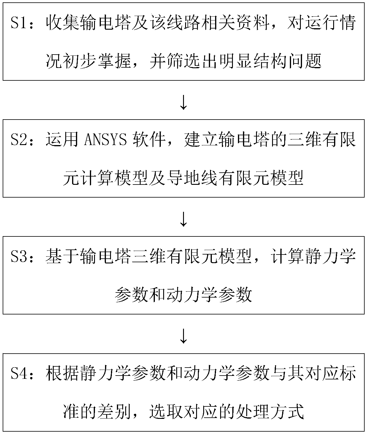
The invention provides a method for evaluating the structural state of a transmission tower. The method comprises the following steps of S1 collecting the relevant data of the transmission tower and the transmission line, initially grasping the operation situation, and screening out obvious structural problems; S2 establishing the three-dimensional finite element model of the transmission tower and the finite element model of a conductor by the ANSYS software; 3 calculating the static parameters and the dynamic parameter based on the three-dimensional finite element model of the transmission tower; S4 according to the difference between the static and dynamic parameters and their corresponding standards, selecting the corresponding treatment mode.. Based on the finite element to evaluate the structural state of the transmission tower, the method is convenient for transmission line maintenance and repair personnel and related scientific research personnel to evaluate the operation stateof the transmission tower, and then take corresponding measures to ensure the structural safety of the transmission tower.

Description

technical field [0001] The invention belongs to the field of transmission tower monitoring, and in particular relates to a method for evaluating the structural state of a transmission tower. Background technique [0002] Power grid transmission tower is a kind of high-rise structure widely used. As an important power engineering facility, it has important economic and social significance to ensure the safe and reliable operation of the main structure system under various loads. However, transmission lines are the "lifeline" of electric energy transmission, and accidents of tower collapse and disconnection occur from time to time. [0003] The structural failure accidents of transmission towers can be roughly divided into three categories. One type is due to the tower being subjected to external forces, such as earthquakes, typhoons, tornadoes, ice-wrapped static forces, dynamics, or combined static and dynamic effects of structural instability or damage caused by exceeding ...

Claims


Application Information

Patent Timeline
Patent Type & Authority Applications(China)
IPC IPC(8): G06F17/50
CPCG06F30/23G06F30/13
Inventor 菅明健杜宝帅张忠文邓化凌李志明张广成张用张华恺
Owner ELECTRIC POWER RESEARCH INSTITUTE OF STATE GRID SHANDONG ELECTRIC POWER COMPANY
Learn More