Welding method and structure for motor end ring and conducting bars

A welding method and bar technology, applied in welding equipment, magnetic circuit shape/pattern/structure, workpiece edge, etc., can solve the problem that the vertical accuracy of the bar and the end face is difficult to guarantee, the interval is difficult to accurately control, and the welding quality needs to be improved, etc. problems, to achieve the effect of reducing the difficulty of welding operation, reducing difficulty, and positioning simple and clear

Inactive Publication Date: 2019-02-19
CSR ZHUZHOU ELECTRIC CO LTD
View PDF8 Cites 2 Cited by
  • Summary
  • Abstract
  • Description
  • Claims
  • Application Information

AI Technical Summary

Problems solved by technology

[0013] 1. There are many silver solders and solders that need to be filled, and the cost of soldering is high
[0014] 2. It is difficult to guarantee the vertical accuracy of the guide bar and the end face, and the welding quality needs to be improved
[0015] 3. The number of guide bars is large, the interval in the annular groove is difficult to control accurately, and the welding operation is difficult

Method used


Image

  • Welding method and structure for motor end ring and conducting bars
  • Welding method and structure for motor end ring and conducting bars

Examples


Embodiment Construction

[0040] Attached below Figures 1 to 2 Embodiments of the present invention are described in detail.

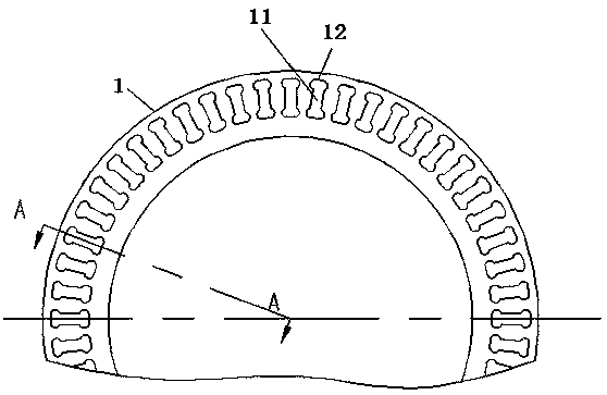
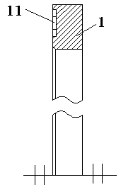
[0041] The welding method of the motor end ring and the guide bar, including the end ring 1 and the guide bar, is characterized in that according to the size of the end of the guide bar, a groove 11 corresponding to the guide bar is processed on the end surface of the end ring 1, and then the guide bar The bar and the groove 11 are welded on the end ring 1 correspondingly.

[0042] like figure 1 As shown, the groove on the end ring is a single groove that corresponds to the guide bar one by one, rather than a full circle of annular grooves.

[0043] One guide bar is welded in one groove, the area of ​​the groove on the end ring is reduced, and the solder is limited in a single groove during welding, ensuring that the melting and solidification of the solder is always limited in a single groove during the welding process, which can Effectively reduce the amount of silver sol...


PUM

PropertyMeasurementUnit
depthaaaaaaaaaa

Abstract

The invention discloses a welding method and structure for a motor end ring and conducting bars. The welding structure comprises the end ring and the conducting bars. The welding structure is characterized in that grooves which are in one-to-one correspondence to the conducting bars are processed in the end surface of the end ring according to the dimensions of the end parts of the conducting bars, wherein the conducting bars and the grooves are correspondingly welded on the end ring. The welding structure reduces area of grooves in the end ring, and welding flux is limited in a single grooveduring welding, so that melting and curing of the welding flux in a welding process are guaranteed to be always limited in single groove, dosage of sliver brazing filler metal and soldering flux can be effectively reduced, welding cost is reduced, the conducting bars are guaranteed to be uniformly spaced and distributed in the peripheral direction of the end ring, the welding positions of the conducting bars are positioned simply and clearly, distance regulating does not need to be manually performed, welding operation difficulty is effectively reduced, and welding efficiency and welding quality for the end ring and the conducting bars is improved.

Description

technical field [0001] The invention relates to a welding method and structure of a motor end ring and a guide bar, which is used for welding the motor end ring and guide bars, and belongs to the technical field of motor manufacturing. Background technique [0002] The motor rotor is also the rotating part in the motor. The motor is composed of two parts: the rotor and the stator. It is used to realize the conversion device of electric energy and mechanical energy and mechanical energy and electric energy. The motor rotor is divided into the motor rotor and the generator rotor. The motor rotor mostly uses cage Type structure, so easy to rotate. [0003] The brazing of the end ring and the rotor guide bar in the manufacturing process of the cage-type motor rotor is an important link in the motor production process, and the quality of the brazing directly affects the performance parameters of the motor. In order to ensure the quality of the product, the end ring brazing struc...

Claims


Application Information

Patent Timeline
Patent Type & Authority Applications(China)
IPC IPC(8): B23K1/002B23K33/00H02K1/22
CPCB23K1/0008B23K1/002B23K33/00H02K1/22
Inventor 杨振中段永华李爽张冬妮龙云峰
Owner CSR ZHUZHOU ELECTRIC CO LTD
Why Eureka
Try Eureka