EGR flow verification system

A flow and control valve technology, applied in fuel injection control, engine control, machine/engine, etc., can solve the problems of inability to guarantee the engine, insufficient engine power, excessive NOx, etc., to shorten the maintenance time, simple structure, and reduce excessive emissions. Effect

Pending Publication Date: 2019-02-19
SINO TRUK JINAN POWER
View PDF7 Cites 1 Cited by
  • Summary
  • Abstract
  • Description
  • Claims
  • Application Information

AI Technical Summary

Problems solved by technology

Although the current EGR control valve can accurately control and measure the EGR flow rate, once the EGR control valve fails and the measurement is inaccurate, the EGR rate of the engine cannot be guaranteed to meet the design requirements, resulting in insufficient engine power or the generation of NOx too many situations

Method used


Image

  • EGR flow verification system

Examples


Embodiment Construction

[0013] The present invention will be specifically described below in conjunction with the accompanying drawings and embodiments.

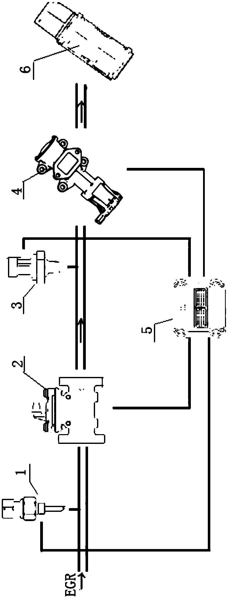
[0014] figure 1 Shown is the structural representation of the present invention.

[0015] The present invention provides an EGR flow verification system, which includes a temperature sensor 1, a differential pressure sensor 2, a pressure sensor 3, an EGR control valve 4 and an engine ECU 5.

[0016] The temperature sensor 1, the differential pressure sensor 2, the pressure sensor 3 and the EGR control valve 4 are sequentially connected to the exhaust gas pipeline, the EGR control valve 4 is connected to the mixer 6, the temperature sensor 1, the differential pressure sensor 2, the pressure sensor 3 and the EGR control valve 4 are respectively connected with the engine ECU5.

[0017] The differential pressure sensor 2 and the EGR control valve are directly fixed in the EGR pipeline with bolts, and the EGR control valve 4 is directly fixed with bol...


PUM


Abstract

The invention discloses an EGR flow verification system. The EGR flow verification system comprises a temperature sensor, a differential pressure sensor, a pressure sensor, an EGR control valve and anengine ECU. The temperature sensor, the differential pressure sensor, the pressure sensor and the EGR control valve are sequentially connected to an exhaust gas pipe. The EGR control valve is connected with a mixer. The temperature sensor, the differential pressure sensor, the pressure sensor and the EGR control valve are each connected with the engine ECU. EGR passes through the temperature sensor, the differential pressure sensor, the pressure sensor and the EGR control valve and enters the mixer. Data measured by the temperature sensor, the differential pressure sensor and the pressure sensor are transmitted to the engine ECU through a wiring harness. By means of the EGR flow verification system, precise verification of the EGR flow can be achieved; the problem that out-of-limit emission is caused by abnormal work of an engine is reduced, and emission of harmful products is reduced; and the fault point can be found rapidly, and the engine maintenance time is shortened. The EGR flowverification system is simple in structure and convenient to arrange.

Description

technical field [0001] The invention relates to a flow verification system, relates to an EGR natural gas engine, and belongs to the technical field of engines. Background technique [0002] EGR (Exhaust Gas Recirculation), that is, exhaust gas recirculation, is to introduce a part of the exhaust gas of the engine into the intake pipe, and enter the cylinder together with the mixed gas for combustion. Mixing exhaust gas into the mixed gas can effectively reduce the combustion temperature and slow down the combustion speed, so it can effectively suppress the formation of NOx. However, because the gas is mixed with exhaust gas, it will affect the combustion performance of the gas and reduce the output power of the engine, so the flow of EGR needs to be strictly controlled. To control the flow of EGR, the focus is on the measurement of EGR flow. Although the current EGR control valve can accurately control and measure the EGR flow rate, once the EGR control valve fails and th...

Claims


Application Information

Patent Timeline
Patent Type & Authority Applications(China)
IPC IPC(8): F02D41/22F02D41/00
CPCF02D41/0047F02D41/221F02D2200/10F02D2200/021F02D2200/02
Inventor 李鹤袁承志周长征蔡士振田玉立王鹏程
Owner SINO TRUK JINAN POWER
Why Eureka
Try Eureka